2788
Proceedings of the 18
th
International Conference on Soil Mechanics and Geotechnical Engineering, Paris 2013
Proceedings of the 18
th
International Conference on Soil Mechanics and Geotechnical Engineering, Paris 2013
2 MATERIALS AND METHODS
2.1
Localization of the Study Area
The refferred construction is located in an adjacent city called
Guará II, Brasília, DF. The design consists of two residential
towers with an underpark garage excavated in such a way that
the three-dimensional spacialization of soil data was justified
because of the great soil variability and because of that the
difficulty in executing the foundations. In such construction, 33
SPT borings were made in a piece of land with 60 m by 150 m
and lately load tests were also made which results were added to
the three-dimensional models.
The differential of that
construction is that a three-dimensional model of bearing
capacity was proposed for it, which was calibrated by the field
load tests.
The UTM coordinates which limit the area are: Xmin =
180.941 m, Xmax=181.001 m, Ymin= 8.246.782 m,
Ymax=8.246.932 m, Zone 23, datum Astro-Chuá with central
meridian of 45º WGr. Figure 1 shows the study area location.
2.2
Geological Context of the Study Area
With the topographical ellevations around 1090-1108 m that
area presents a plan topography. The river basin of Riacho
Fundo is the fundamental factor of the local landscape
evolution.
The original rock, with a low degree of
metamorphism shows an ordinary bright probably due to the
sericita presence. The lithological characteristics and the
geographycal situation of such occurance suggests its
posisioning in the Fácies Ardósia (MNPpa), according to the
statigraphical sequence proposed by Faria (1995).
2.3
Three-dimensional Modeling of the Geotechnical Data
The data modeling in a three-dimensional environment requires
some methodological procedures (Silva & Souza, 2009). The
more used parameters for three-dimensioning modeling are the
lithological ones in the case of rock descriptions; statigraphical
ones to describe soil layers or excavating material; Nspt values
or any numerical measurement (geophysical data, geochemical
data, strength parameters among others) which can be described
in a local manner or between pre-defined intervals; water table;
among other parameters that can be adapted to the RockWorks
15 software
I this case, the adopted calculating method for the
foundations, continuous flight auger piles, was proposed by
Decourt & Quaresma (1978). By the access to the geotechnical
dimensioning and results of the load tests, load test models were
generated for 50 and 60 centimeter diameter piles.
It is important to mention that the target of the load test was
to calibrate the results obtained from the foundations’
calculations, once the adjustment parameters for the shaft and
tip calculation bearing capacity were initially assumed by the
designer, and letting the model to spacialize the results to make
possible a proper ajustment for the dimensioning adopted
method. That is, it was not the objective of the work to review
any foundation calculating method, but to show that it is
possible to manage other types of three-dimensioning models
and their applications on the field in the most direct way.
2.3.1
Data Log
The first step for the three-dimensional modeling is the data log
in a data bank of the computer software which will be
responsible for the modeling. The data log of the borings in the
RockWorks 15 software is done in a sequence as follows:
1. Location of the borings. A simple procedure which requires
the name of the boring, The East and North coordinates (x,y)
and the elevation of the top of the boring (coordinate z), besides
the total depth achieved by the drilling. If it is necessary, a
symbol can be added represent the borings in the generated bi-
dimensional charts.
2. After the location of the borings, the soil profile or the
statigraphic log can be done. However, it is very important to
evaluate all borings and to establish which will be the soil
profile to be used by the model, which procedure can be a
complex one because of the soil variability, and in some cases it
will be impossible to elaborate the statigraphic model due to
such variability.
3. Description of the punctual numerical values. That concerns
to insert the numerical values described in the borings, normally
the Nspt values.
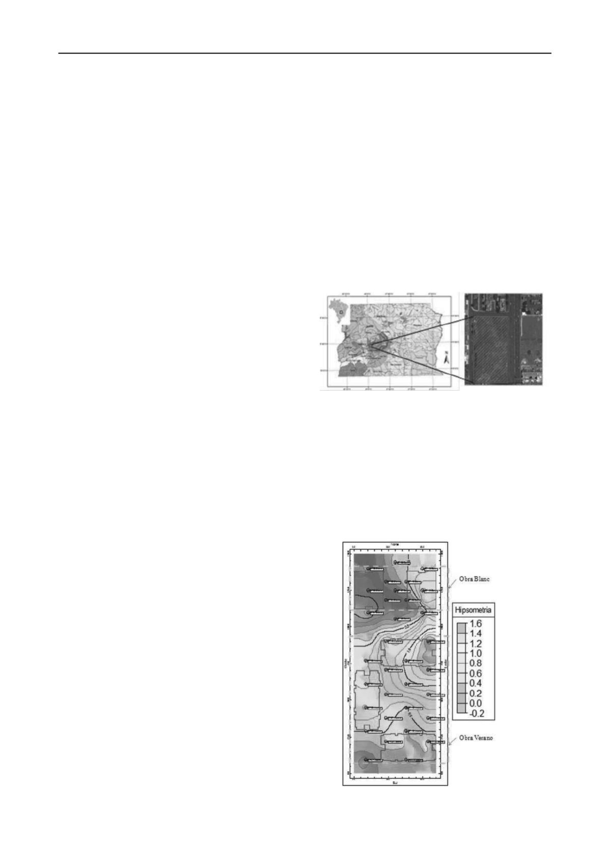
3 RESULTS
The first result obtained for the case study was the basic chart
with the information concerning the borings’ location, the
“Verano” and “Blanc” constructions which gave the
name of
the case study, and the hipsometria values for the piece of land.
In the case of this construction there was no compatibility of
datum and the construction was not geologically referred, that
is, the modeling was done based on the local reference, because
the construction made its choice based on such reference.
It can be observed in Figure 2 the basic chart with the
information geologically referred. It is important to mention that
ground is general plan and later it was excavated 4 meters
below because of the execution of the construction
undergrounds.
Figure 1. Location of the study area.
Figure 2. Hipsométrica
chart with the SPT borings’ location and the
constructions’ location
.


