1430
Proceedings of the 18
th
International Conference on Soil Mechanics and Geotechnical Engineering, Paris 2013
movement of the anchor block is clearly observed in Figures 8
and 9. It is evident that the rigid anchor block introduces a
kinematic constraint to the propagating fault slightly reducing
the magnitude of displacements in the y- and z-directions within
the footprint of the block in comparison with the free-field
motion. The ground moves slightly towards positive x-direction
in the footwall side in the free-field model as seen in Figure 9
whereas this does not occur when the anchor block is placed.
5 STRUCTURAL IMPLICATIONS
The anchor block only displaces rigidly due to its stiffness.
Geometrical changes to the main cable alignment due to the
fault-induced anchor block displacement are acceptably small.
The longitudinal inclination and the tilt across the anchor block
mean that gravity forces to the cable structures are slightly out
of the plane in which they are aligned. However, the gravity
load is negligible compared with the cable pull from the
suspension bridge.
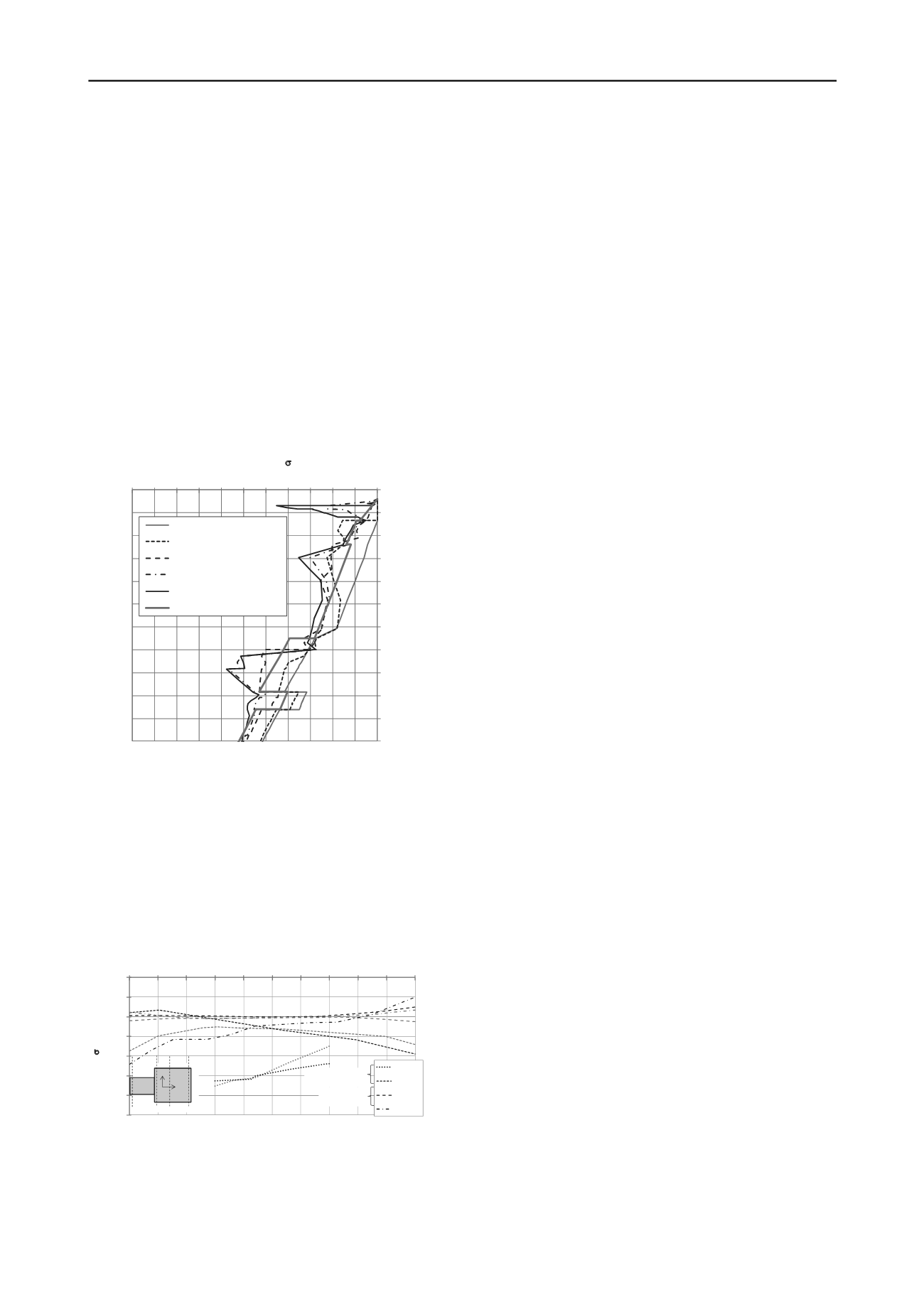
4.2
Horizontal stresses acting on the block
The effective horizontal normal stresses (σ'
y
) acting on the
anchor block along the line at x=-55 m and y=10.5 m on the
hanging wall are plotted in Figure 10. At this location, it can be
observed that the anchor block construction, fill placement and
application of the structural loads lead to a stress increase
compared to the in-situ stresses. The fault movement increases
the stresses further. The final stresses at the chosen location are
in general larger than the free-field stresses. Similar tendencies
have been observed for sections along the anchor block.
The only significant effect of the rotation of the anchor block
is the slight rotation of the main cables. The plan rotation leads
to a sideway sway of the main cable relative to the saddle
orientation of the same degree. The anchor block inclination of
1:250 in combination with the 500 mm downward movement
and the shortening of the side span result in a slight and
negligible roll in the cable saddle. The transverse inclination of
the anchor block cross section of 1:1000 is without any
significant distortion of the main cable geometry.
6 CONCLUSION
‐50
‐45
‐40
‐35
‐30
‐25
‐20
‐15
‐10
‐5
0
5
‐550 ‐500 ‐450 ‐400 ‐350 ‐300 ‐250 ‐200 ‐150 ‐100 ‐50 0
Level (m)
HorizontalStress,
'
y
(kPa)
Step1 ‐ In‐situStresses
Step2 ‐ AnchorBlock
Step3 ‐ Fill Placement
Step4 ‐ Structural Loads
Step5 ‐ Fault Displacement
K0(free‐field)
The interaction between oblique-slip fault movement and a
suspension bridge anchor block has been investigated using
PLAXIS 3D. Innovative boundary modelling has allowed the
effects of the fault to be modelled without loss of consistency
within a calculation volume of manageable size.
The effect of fault displacements on the horizontal stresses
acting on the anchor block side walls is minor. The robust and
thick base of the anchor block effectively resists the stress
changes on the base of the anchor block due to the fault
movement.
7 ACKNOWLEDGEMENTS
Figure 10. Effective horizontal normal stresses based on construction
sequence.
The authors gratefully acknowledge the permission by the
owner NÖMAYG Joint Venture/Nurol-Özaltn-Makyol-Astaldi-
Yüksel-Göçay, and the Contractor IHI Infrastructure Systems
CO., Ltd. to publish this paper.
The stresses show rough and irregular patterns due to the
unavoidable coarseness of the mesh of this size and the lack of
interface elements.
8 REFERENCES
4.3
Total stresses at the base of the anchor block
The changes in vertical total stresses at z=-15m due to fault
movements are shown in Fig. 11. It can be observed that the
fault movement causes an increase of the stresses on the +y
sides of the anchor block in the sections x = -55 m and -14 m.
Gazetas G., Anastasopoulos I. and Apostolou M. 2007. Shallow and
deep foundations under fault rupture or strong seismic shaking. In
Earthquake Geotechnical Engineering
, Pitilakis (ed), Ch. 9, 185-
215, Springer.
Anastasopoulos I., Gazetas G., Bransby M.F., Davies M.C.R and El
Nahas A. 2007. Shallow foundation over rupturing normal faults:
analysis and experiments, 4th ICEGE, June 25-28,Thessaloniki.
Gazetas G., Pecker A., Faccioli E., Paolucci R. and Anastasopoulos I.
2008. Design recommendations for fault-foundation interaction.
Bulletin of Earthquake Engineering
, 6 (4), 677-687.
-1750
-1500
-1250
-1000
-750
-500
-250
0
-25 -20 -15 -10 -5 0 5 10 15 20 25
z
(kPa)
y-coordinates (m)
x=-55m
x=-14m
x=15m
x=55m
Footwall
x=-55
x=-14
x=15
x=55
x
y
Hanging wall
Faccioli E., Anastasopoulos I., Gazetas G., Callerio A. and Paolucci R.
2008. Fault rupture–foundation interaction: selected case histories
Bulletin of Earthquake Engineering
, 6 (4), 557-583.
Anastasopoulos I., Gazetas G., Drosos V., Georgarakos T. and
Kourkoulis R. 2008. Design of bridges against large tectonic
deformation.
Earthquake Engineering & Engineering Vibration
, 7
345-368, 2008.
Loli M., Bransby M.F., Anastasopoulos I., and Gazetas G. 2012.
Interaction of caisson foundations with a seismically rupturing
normal fault: centrifuge testing versus numerical simulation.
Géotechnique
, 62 (1), 29-44.
Figure 11. Total vertical stresses at the base of the anchor block before
(grey lines) and after (black lines) fault movement.
The opposite behaviour can be observed in the section x=55
m, while no major stress changes occur in the section x=15 m.
Due to the anchor block rotations, the vertical stresses at the
bottom of the anchor block show a more uneven stress
distribution after fault movement.


