1429
Technical Committee 203 /
Comité technique 203
4 ANALYSIS RESULTS
4.1
Surface displacements
Figure 4 shows the free field deformed mesh. The boundary
conditions for the large numerical model affect the
displacements close to the boundaries but not significantly the
displacements around the anchor block. This is because the
"cushion" material volumes deform due to the prescribed fault
displacement. It is observed that boundary conditions have
limited impact on the anchor block thanks to the low-stiffness
"cushion". The displacement pattern agrees with typical normal
faulting patterns (e.g. Anastasopoulos et al., 2007) as the anchor
block follows the movement of the hanging wall.
Figure 5 shows the deformed mesh in a soil-anchor block
model. The anchor block moves horizontally due to lateral
component of the displacement.
Figure 4. Free-field deformed mesh (scaled up 175 times).
The anchor block shows a forward movement combined with
a rotation (see Fig. 5). It is subject to torsion around the z-axis
where the lateral fault movement occurs, and y-axis mainly
because the block follows the movement of the hanging wall.
Figure 5. Soil-anchor block deformed mesh (scaled up 150 times).
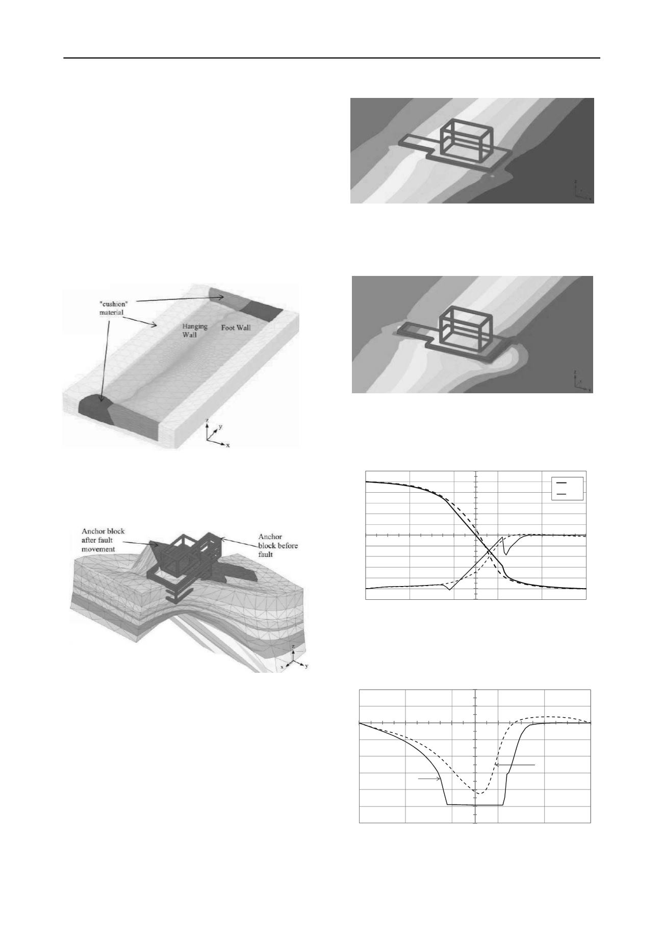
Figures 6 and 7 present the y- and z-displacement fields at
the ground surface, respectively. As a result of fault movement,
the anchor block is subjected to maximum differential
horizontal (along y-axis) and vertical displacements between the
left and right edges of
u
y
= 560 mm and
u
z
= 490 mm.
The differential vertical displacement
u
z
= 490 mm
corresponds to the applied vertical fault displacement of
500 mm meaning that the anchor block has a tilt of 1:250 in the
direction of the bridge (i.e. x-axis). The rotations of the block
around the y- and z-axis are 0.27
o
and 0.23
o
, respectively .
Hence, the vertical displacements as opposed to the horizontal
displacements, at the outcrop are transferred directly to the
surface. Figures 8 and 9 compare the u
x
, u
y
and u
z
displacements
at the ground surface for the free field and the anchor block-soil
models along a line in the x-direction passing through the centre
of the soil-anchor block.
Figure 6. u
y
displacement field.
The difference between free-field and the anchor block-soil
model displacements at the anchor block boundaries are around
u
y
= 90 mm and
u
z
= 30 mm at left corner of the block and
u
y
= 35 mm and
u
z
= 64 mm at the right corner of the block.
Figure 7. u
z
displacement field.
The tilt of the anchor block around the x-axis due to fault
movement is approximately 1:1000, which is only 25% of the
tilt around the y-axis.
‐600
‐500
‐400
‐300
‐200
‐100
0
100
200
300
400
500
600
‐250
‐150
‐50
50
150
250
displacement (mm)
x‐coordinates(m)
u_y
u_z
Figure 8. Horizontal (u
y
) and vertical (u
z
) displacements along the centre
of the anchor block at the ground level. Dotted and solid lines represent
displacements for free field and soil-anchor block model, respectively.
The discontinuity in vertical downward movement in the
vicinity of the right hand side (footwall side) of the block
implies separation between the soil and the block developing.
‐300
‐250
‐200
‐150
‐100
‐50
0
50
100
‐250
‐150
‐50
50
150
250
u
x
(mm)
x‐coordinates(m)
Free-field
soil-anchorblock
model
Figure 9. Horizontal displacements, u
x
, in the x-direction along the
centre of the model at the ground level.
The anchor block also moves 250 mm in the x-direction
following the movement of the hanging wall (Fig. 9). The rigid
400 mm
300
0
-400 -300
-450
-400
-300
-50
-150


