1262
Proceedings of the 18
th
International Conference on Soil Mechanics and Geotechnical Engineering, Paris 2013
X-Acc. (g)
Time
-0.1
-0.2
-0.3
-0.4
0.0
0.1
0.2
0.3
0.4
0
5
10
15
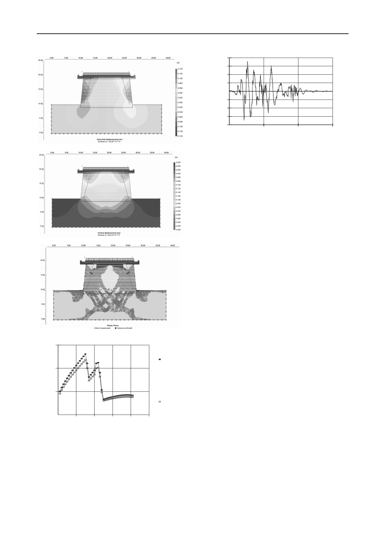
Figure 17 Time history (x-acceleration) - output.
Figure 13 Horizontal displacements.
The conclusion of this calculus is that the maximum
horizontal acceleration at the top of the embankment is 0,35g.
From stability analysis we can see that the structure is unstable
having a factor of safety 0,995.
4 CONCLUSIONS
a) Model 1: the maximum total displacement is 280mm (at
the edge the sidewalks - Fig. 6). As it can be seen in Fig.
10 the plastic points appear at the edges of the
embankments and in the central part of soil foundation at a
approx. depth of 5m. Also, a very important notice is that
the plastic points also appear at the edge of the
embankment at maximum 1m around the body of backfill.
Figure 14 Vertical displacements.
b) Model 2: maximum total displacement is 33,5mm (at the
edge the sidewalks - Fig. 11). As it can be seen in Fig. 15
the plastic points appear at the edges of the embankments
and in the central part of soil foundation at a approx. depth
of 10 m. Also, a very important notice is that the plastic
points also appear at the edge of the embankments at
around 5m around the body of backfill. From Stability
analysis we can see that the structure is almost permanent
at limit having a factor of safety 1,105. Fig. 16 show us
that the embankment structure has a very small reserve in
strength for seismic action.
c) Model 3: the maximum horizontal acceleration at the top
of the embankment is 0,35g. From stability analysis we can
see that the structure is unstable having a factor of safety
0,995. Fig. 17 shows that the embankment structure has no
reserve in strength.
Figure 15 Plastic points.
Shear Strength
Shear Mob.
ShearResistance
Slice#
0
50
100
150
0
10
20
30
40
50
d) All tests and calculations made underline high strain and
low bearing capacity of flooded state soil foundation.
e) Soil foundation is high compressibility terrain with great
sensibility at moistening under stresses according to
specific macrostructure.
f) To realize this works uncohesive soils are recommended;
all tests on Bahlui clay show that this material is not proper
to be used safely for embankments.
5 REFERENCES
Bowles, J. E. [1997] “
Foundation analysis and design
”, Ed.
McGraw-Hill international editions, Civil Engineering Series,
Fifth Editions.
Figure 16 Shear resistance versus slice.
b) MODEL 3. Seismic response due to earthquake with
foundation soil in flooded state.
Chirica, A. [1995]. “
Tasarea şi cedarea pământurilor
macrostructurate
”, Editura UTCB
For this model GEOSLOPE is used for analysis. Here a
dynamic analysis was performed according to the romanian
seismic code P100-2006. A scaled accelerogram was used with
peak ground acceleration of 0,2g and 15s. Time increment was
0,02s and results were saved at every 10 steps.
Ieremia, M. [1998]. “
Elasticitate, plasticitate, neliniaritate
”
Ed. Printech, Bucuresti.
Tenea, D.
[2007]. “
Contributii privind metodele de tratare si
ranforsare a pamanturilor cu structura metastabila in cazul
cailor de comunicatie
”, Ed. UTCB.


