1257
Technical Committee 202 /
Comité technique 202
simplified design scenario shown in Figure 2 if ground
treatment is not carried out. In the absence of ground treatment,
equilibrium solutions could not be obtained and the likely
failure mechanisms are shown in Figure 3. The predicted failure
mechanism involves concentrated shear strains mobilised along
the base of the marine clay layer due to the constant strength
assumption. The overall stability is directly dictated by the
elevation of the soft marine clay layer which controls the
overburden pressure exerted on the potential failure soil mass.
To enhance the overall stability, jet grouting works was
proposed. The potential working principle of the jet grout
columns has been studied by finite element analyses. The
technique of strength reduction has been used in the analysis to
quantify the margin of safety and to identify the most critical
failure mechanism of the design scheme. In the analyses,
several rows of 2 m diameter discrete jet grout columns which
pass through the marine clay and alluvium layers are assumed.
The uniaxial compressive strength (UCS) and the Young’s
modulus of the jet grouted material are assumed to be 2 MPa
and 300 MPa respectively. Due adjustment of these parameters
have been made in the plane strain models.
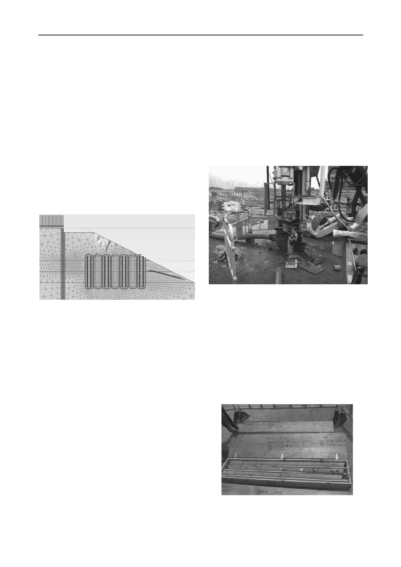
Figure 4. Finite element prediction for bermed excavation with jet
grouting - incremental shear strain distributions at failure.
Figure 4 shows the incremental shear strain distributions at
failure when soil strengths have been reduced by a factor of
1.45 through strength reduction calculations. It can be seen that
the most critical failure mechanism no longer involves a sliding
plan along the base of the marine clay layer due to the presence
of the jet grout columns. Instead, a local failure in the marine
clay and alluvium is observed.
In the analysis, the jet grout columns are modeled as a non-
porous elastic perfectly plastic material, with the maximum
shear strength governed by the Mohr-Coulomb failure criterion.
Jet grouted material is brittle and therefore the mobilised shear
strains in the jet grout columns have been calculated to ensure
sufficient strength can be mobilised at small deformation. A
limiting criterion of maximum shear strain of 0.5% has been
adopted.
The design scenario depicted in Figure 2 is a gross
simplification of the actual site conditions. It conservatively
considers the adverse effects of the presence of soft marine clay
on the overall stability. The actual characteristics of the marine
clay, including its strength, thickness and elevation, may vary
across the site. The finite element analyses merely confirm the
feasibility of the design scheme under an extreme condition.
The actual amount of jet grout columns to be installed is
determined by considering the local ground conditions,
excavation profiles and the characteristics of the marine clay.
The key design criteria are the overall safety margin of the
excavation including the slope in front of the wall, the
mobilised deformation in the jet grouted material as well as the
structural forces induced in the diaphragm wall. Verification of
the assumed material parameters for the jet grout columns is
described in the next section.
3 PERFORMANCE VERIFICATION
Although jet grouting has been used widely in many parts of the
world, it has not been common in Hong Kong. Therefore, not
much field data was available. As such, a site trial was carried
out before commencement of the actual jet grouting works. The
purpose of the site trial is to determine the control parameters of
the grouting operation, for example, the grout pressure, nozzle
size and lifting rate, etc. In addition, the site trial serves to
confirm that the assumed design strength and stiffness of the jet
grouted materials can be obtained. A total of twelve trial jet
grout columns were constructed using different combinations of
operation parameters. A photo showing the jet grouting works is
shown in Figure 5. The entire process is fully automated with
all the operation parameters shown on a digital display panel.
Figure 5. Plant used for jet grouting works with fully automated control
system.
A comprehensive post-grouting investigation was carried
out. This included multiple full-depth coring in the trial jet grout
columns, laboratory testing of the core samples and in-situ
pressuremeter tests in the core holes. Core samples were
obtained at differnet depths and at different locations in order to
confirm that an effective diameter of 2 m could be acheived.
The core samples were tested to obtain the Young’s modulus
and the UCS of the specimens. In-situ pressuremeter tests were
conducted in the core holes to measure the stiffness of the
grouted zone. The final operation parameters of the jet grouting
works were determined according to the results of site trial.
For working jet grout columns, full-depth corings were
obtained at a particular sampling frequncy as a quality control
measure. Typical cores are shown in Figure 6.
Figure 6. Typical core sample obtained from jet grout column


