1256
Proceedings of the 18
th
International Conference on Soil Mechanics and Geotechnical Engineering, Paris 2013
2 DESIGN OF THE DEEP EXCAVATION
The 30 m deep excavation at WKT has a plan area of
approximately 550 m by 220 m, and is surrounded by high-rise
residental and commerical buildings in West Kowloon – an
urban area of Hong Kong. Construction of large diameter bored
piles and rock-socketted steel H-piles for supporitng the station
structure and the perimeter diaphragm wall was carried out
before excavation commenced. The diaphragm wall serves as
the temporary retaining structure for the deep excavation, the
permenent wall of the station structure, as well as a load bearing
wall to support the vertical load from the superstructure. This
Section describes the ground conditions of the site, the
construction seqenence and the design considerations of the
deep excavation.
2.1 Ground conditions
The solid geology within the site area comprises Kowloon
Granite from the Cretaceous Period of the Mesozoic Era which
is a monzogranite pluton centered on Kowloon and Hong Kong
Island. The superficial deposits include fill and transported
materials such as alluvium, colluvium, marine deposits,
estuarine deposits and the like.
Reclamation fill has been placed on the site following the
West Kowloon reclamation works carried out in the 1990s. The
fill comprises the reclamation deposits and the remnants of the
old seawalls, old breakwaters, revetments, old ferry pier and
existing layers of building debris and rock fill. The in-situ
deposits include weathered rock and the soil derived from the
weathered rock such as saprolite and residual soil (i.e. the Grade
VI material according to GEO (1988)). Variably jointed rock
and soil masses with different proportions of rock and soil are
present within the in-situ deposits.
The site topography prior to the bulk excavation is generally
characterised as flat and the average ground level is at about
+5.5 mPD. The available groundwater level records from
standpipes and vibrating wire piezometer indicate that the
highest recorded groundwater level ranged from +1.56 mPD to
+3.60 mPD and the lowest groundwater level recorded ranged
from -1.29 mPD to +1.94 mPD.
2.2 Construction sequence
Excavation and construction of the station structure is carried
out by two separate contractors who adopt different construction
methods. The contractor on the northern side adopts open cut
excavation (see Figure 1) which is then followed by bottom-up
construction. On the southern side, the contractor adopts top-
down construction for the top two levels of slabs and then
changes to bottom-up construction for lower levels.
The focus of this paper is the open cut excavation carried out
near the northern part of the site. Upon completion of the
foundation works and diaphragm wall construction, jet grouting
was carried out at locations where soft marine clayey deposits
are present which adversely affect the stability of the bermed
excavation. After sufficient strength had been gained in the jet
grouted material, temporary cut slopes at a gradient of 1 on 2
were formed in front of the diaphragm wall. This was followed
by bottom-up construction of the central core of the station
structure. Construction of the entire structure would then be
completed by top-down method between the diaphragm wall
and the core station structure where the temporary slopes are
gradually removed and replaced by reinforced concrete slabs
connecting the diaphragm wall to the core station structure.
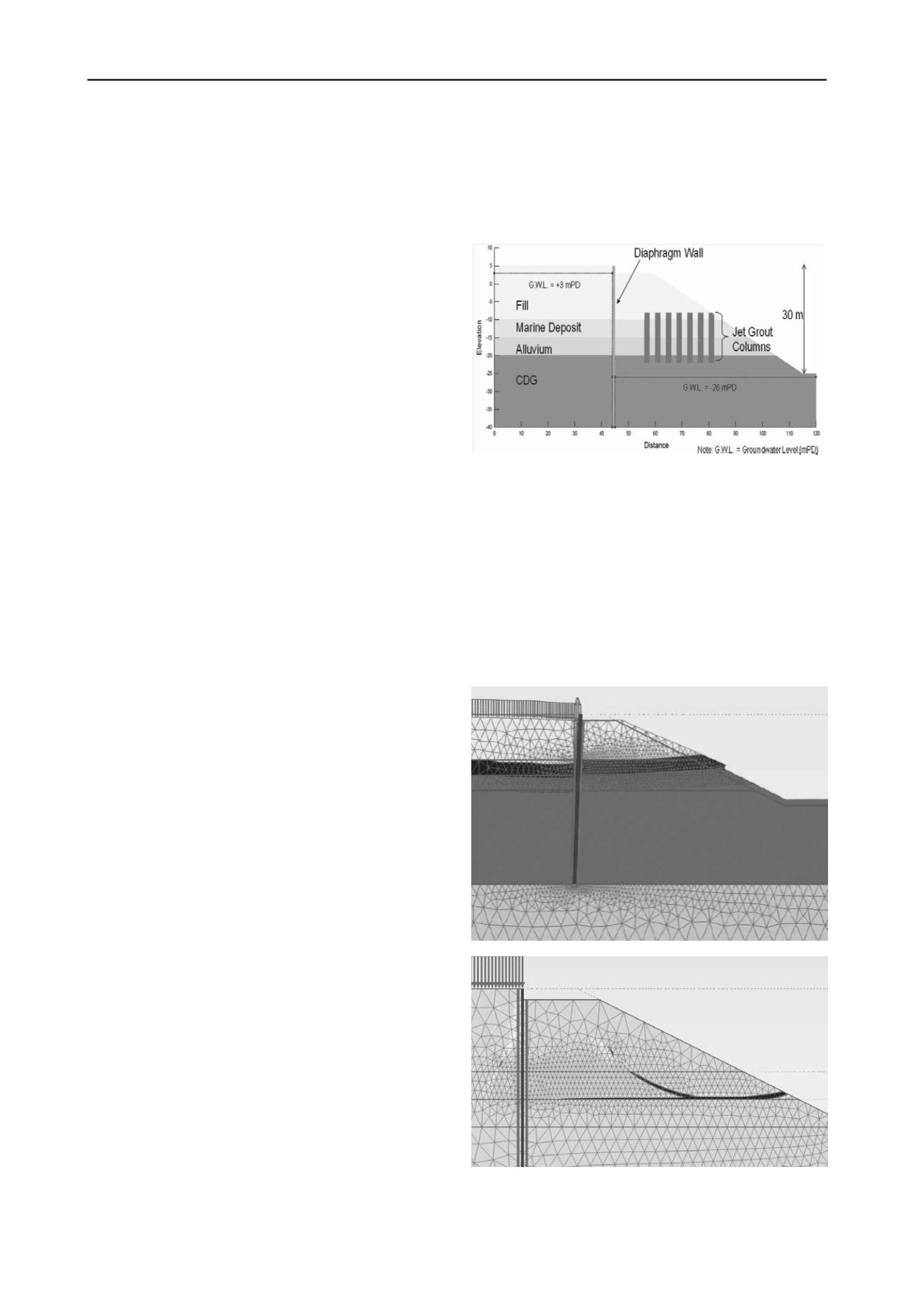
2.3 Design considerations
Figure 2 shows a simplified design scenario which illustrates
the design concept. The diaphragm wall and the soil berm are to
support an excavation with a maximum depth of approximately
30 m. Since the diaphragm wall is designed as a foundation
element for vertical loading, the wall is founded on the bedrock
with a nominal embedment of 300 mm. The sufficiency of the
embedment depth of the wall has been checked by trial wedge
methods. For areas with a shallow rockhead, mini piles, denoted
as shear pins, were constructed beneath the base of the
diaphragm wall to increase the resistance against overturning.
Figure 2. Simplified design scenario of bermed excavation design with
ground treatment by jet grouting.
The trial wedge method considers the soil berm as a passive
support as far as stability of the embedded wall is concerned.
The stability of the soil berm has to be considered separately.
The marine deposits sandwiched between the reclamation fill
and alluvium consist of interbeded cohesive and granular
materials. The cohesive portion typically comprises of clay and
in places silt with various proportion of sands and gravels. The
undrained shear strength ranged from a few kilopascals to >200
kPa. A general design value of 30 kPa was adopted, except for
marine clay at shallow depths where a lower value of 20 kPa
was used.
(a)
(b)
Figure 3. Predictions of failure mode from finite element analysis (a)
total deformation, (b) incremental shear strain distributions
Finite element analyses have been conducted using Plaxis to
predict the behaviour of the bermed excavation for the


