1261
Technical Committee 202 /
Comité technique 202
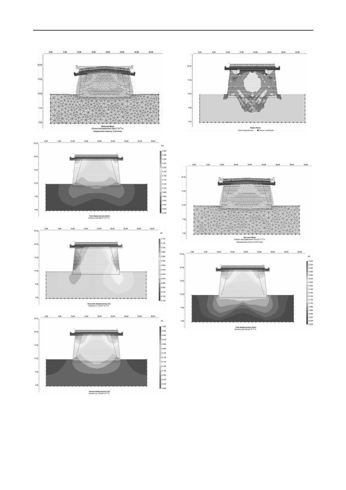
Figure 6 Deformed mesh.
Figure 7 Total displacements.
Figure 8 Horizontal displacements.
Figure 9 Vertical displacements.
The conclusion of this calculus is that the maximum total
displacement is 280mm (at the edge the sidewalks - Fig. 9). As
it can be seen in Fig. 10 the plastic points appear at the edges of
the embankments and in the central part of soil foundation at a
approx. depth of 5m. Also, a very important notice is that the
plastic points also appear at the edge of the embankments at
maximum 1m around the body of backfill.
Figure 10 Plastic points.
a) MODEL 2. Model with foundation soil in flooded state.
This 2
nd
model is taken into consideration the flooded state
of materials.
Figure 11 Deformed mesh.
Figure 12 Total displacements.
The conclusion of this calculus is that the maximum total
displacement is 33,5mm (at the edge the sidewalks - Fig. 12).
As it can be seen in Fig. 15 the plastic points appear at the edges
of the embankments and in the central part of soil foundation at
a approx. depth of 10 m. Also, a very important notice is that
the plastic points also appear at the edge of the embankments at
around 5m around the body of backfill. From Stability analysis
we can see that the structure is almost permanent at limit having
a factor of safety 1,105. Fig. 17 show us that the embankment
structure has a very small reserve in strength for seismic action.


