 
          1268
        
        
          Proceedings of the 18
        
        
          th
        
        
          International Conference on Soil Mechanics and Geotechnical Engineering, Paris 2013


            a


            s


            x


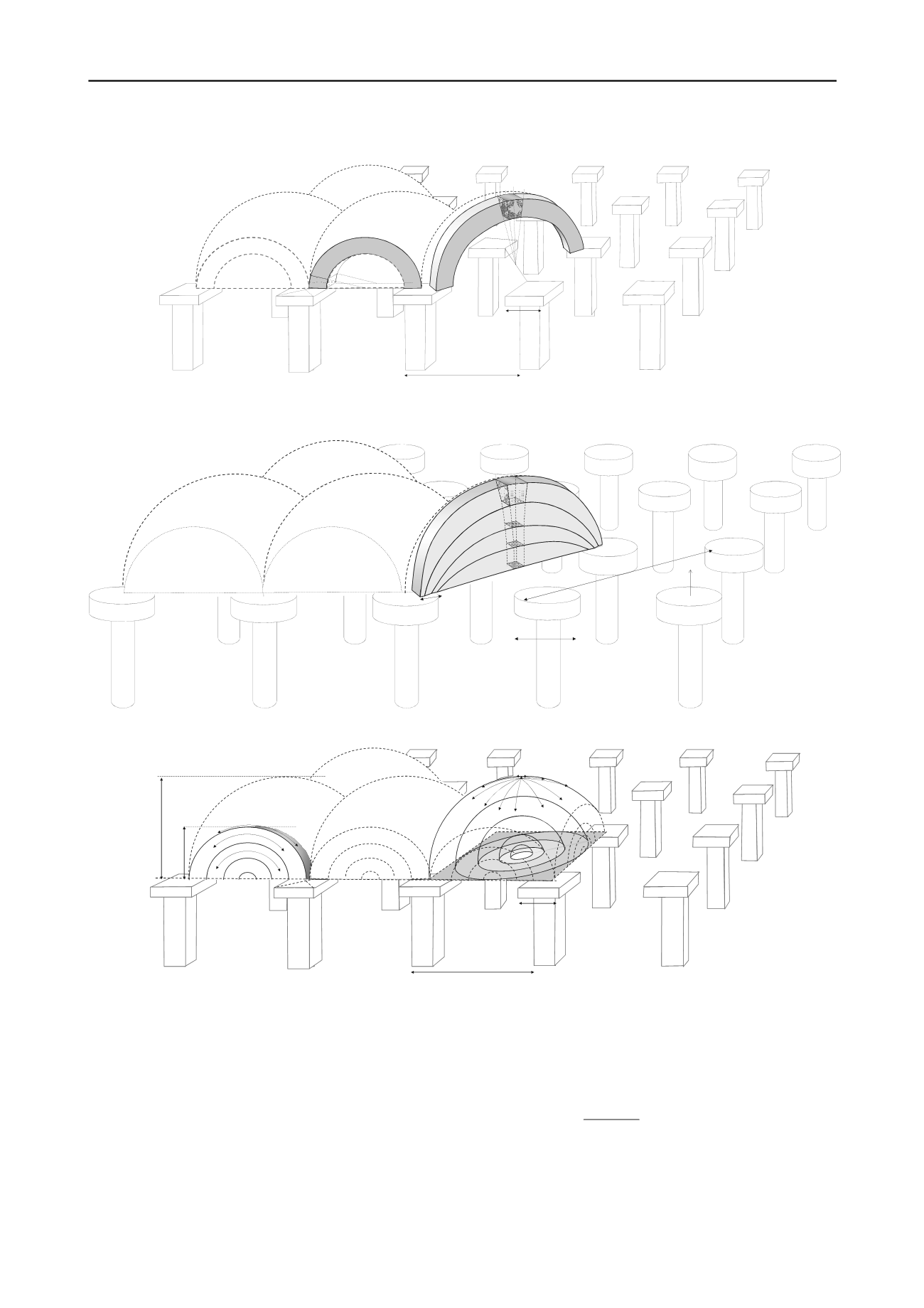
          Figure 2. Hewlett & Randolph (1988) consider the ‘crown’ element of the diagonal arch and the ‘toe’ element (just above the pile cap) of the plane
        
        
          strain arch as indicated in this figure.


            s


            d


            d


            d/2


            z


          Figure 3. Zaeske (2001) considers the equilibrium of the crown elements of the diagonal arches


            s


            x


            a


            H


            g3D


            H


            g2D


          Figure 4. Van Eekelen et al. (2013b), the Concentric Arches Model. The load is transferred along the 3D hemispheres (right hand side) towards the GR
        
        
          strips and then via the 2D arches (left hand side) towards the pile caps
        
        
          A third model is the concentric model presented by Van
        
        
          Eekelen et al. (2013b). Figures 2 to 4 present these three models
        
        
          and are presented in the following sections.
        
        
          3 HEWLETT AND RANDOLPH (1988)
        
        
          Hewlett & Randolph (1988) based their model on 3D door trap
        
        
          tests, without geosynthetic reinforcement. Their analytical
        
        
          model consists of a series of thick-walled 3D-shells, or arches,
        
        
          in the embankment. They consider two arch elements
        
        
          separately: a ‘crown element’ and an element just above the pile
        
        
          cap, the ‘toe’  element, as shown in Figure 2 and Figure 5. For
        
        
          the toe element, the pile load (


            A


          ) is calculated by assuming
        
        
          radial equilibrium of the crown element in the plane strain arch
        
        
          (left in Figure 2) and assuming that the principal stresses follow
        
        
          the arches with


          the major principal stress and


            r


          the minor
        
        
          principal stress and that the arches are in a nearly-plastic
        
        
          situation:
        
        
          1 sin
        
        
          1 sin


            p r


            K


            r


          (1)
        
        
          Where


          (kPa) is the tangential stress,


            r


          (kPa) is the radial
        
        
          stress,


            K


            p


          (-) is the Rankine passive earth pressure coefficient
        
        
          and


          (
        
        
          o
        
        
          ) is the friction angle. The pile load (A) is obtained by
        
        
          integrating


          over the pile area, indicated in Figure 5. For the
        
        
          crown element, the vertical stress


          r;i
        
        
          below the crown is
        
        
          calculated using equilibrium of the crown element in the 3D