852
Proceedings of the 18
th
International Conference on Soil Mechanics and Geotechnical Engineering, Paris 2013
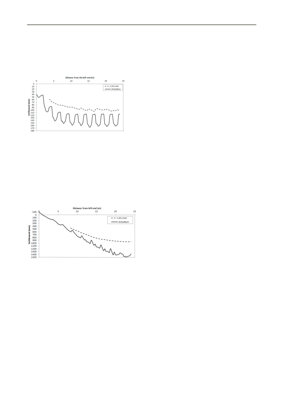
to clear spacing ratios. One embankment is 5.5 m high and other
one is only 2.5 m high. The columns have 1 m diameter and the
centre to centre spacing is 2.5 m in each case. The computed
settlement profiles at the crest and the base of the embankment
during 30 years of service life are shown in Figures 6 and 7 for
low (2.5 m) and high embankments (5.5 m), respectively.
Figure 6. Settlement profile for 2.5 m high embankment.
Figure 6 clearly illustrates humps and depressions at the
crest of the low embankment. Consequently overall punching
failure is possible and this might be the crucial factor in
determining the loss of serviceability of the embankment.
Therefore overall punching is critical when the embankment
height is low.
For the high embankment, even though there is a
considerable differential settlement at the base of the
embankment, it has not been transferred to the crest of the
embankment and produced a fairly even embankment crest
(Figure 7) showing the possibility of local punching failure.
Therefore embankments with higher fill thickness relative to the
column spacing are vulnerable to local punching failure.
Figure 7. Settlement profile for 5.5 m high embankment.
Placing a stiffer geo-membrane immediately on top of the
columns can mitigate local punching failure. Overall punching
failure can be minimised by increasing the efficacy of columns,
area ratio of columns, stiffness of the geosynthetic, thickness of
the load transfer platform by placing more layers of
geosynthetic, and embankment height relative to the column
spacing to develop effective soil arching.
From the numerical results, it could be identified that the
critical height to clear spacing ratio is important in controlling
the overall punching shear failure. This ratio can be used to
ascertain the development of full arching within the fill layers
and thereby to ensure that there are no localized differential
settlements at the crest of the embankment. However, the
critical height defined in current design guidelines is not
consistent.
4.3 Failure due to excessive total foundation settlement
According to Figure 7, it is clear that for high embankments,
excessive total foundation settlement is more crucial than the
differential settlement. Excessive foundation settlement can be
more problematic for high embankments especially with
floating DCM columns where columns penetrate partly into the
clay layer without reaching a stiff base layer. Therefore,
embankment design practice should also aim to prevent failure
due to excessive total foundation settlement.
5 CONCLUSIONS
This paper investigated possible failure modes for GRCS
embankments. The finite element results show that the bending
failure is a critical failure mode for internal stability. Once the
plastic hinges are formed, the embankment fails due to
propagation of a slip surface, which is mainly governed by the
tensile strength of the columns. Some weaknesses in existing
analytical equations for calculation of stability against bending
failure are identified and parameters to be considered for a new
stability calculation are proposed. Overall punching failure is
critical for low embankments and local punching failure is
crucial for high embankments. It is important to establish a
reliable equation for the critical height, considering different
column layouts and geometries to avoid overall punching
failure. High embankments are vulnerable to excessive total
foundation settlement and therefore necessary precautions
should be taken in the design process. Overall this paper
identified some failure modes to be considered in the
development of design procedures to evaluate the overall
stability of GRCS embankments and proposed some future
research directions to improve the current design practice.
6 ACKNOWLEDGEMENTS
The authors would like to acknowledge the financial support for
this research provided by the Australian research council and
Coffey Geotechnics Pty Ltd under LP099058.
7 REFERENCES
Broms, B.B. 2004. ‘Lime and lime/cement columns’, in
Ground
Improvement
Ed. Moseley, M.P. and Kirsch, K. Spon Press,
London, 252-330.
CDIT (Coastal Development Institute of Technology). 2002. ‘
The Deep
Mixing Method: Principle, Design and Construction’
, A.A.
Balkema: The Netherlands.
EuroSoilStab 2002. ‘
Development of Design and Construction Methods
to Stabilise Soft Organic Soils’
. Design Guide Soft Soil
Stabilization, CT97-0351, Project No: BE 96-3177.
Kitazume, M. 2008. ‘
Stability of group column type DM improved
ground under embankment loading behavior of sheet pile quay
wall’
, Report of the port and airport research institute, Nagase,
Yokosuka,Japan, 47(1): 1-53.
Kitazume, M. and Maruyama, K. 2007. 'Internal stability of group
column type deep mixing improved ground under embankment',
Soils and Foundations,
47(3):437-455.
Navin, M. 2005.
'Stability of embankments founded on soft soil
improved with deep mixing method columns'
, Doctor of Philosophy
thesis, Virginia polytechnic institute and state university.
Terashi, M. 2003. 'The state of practice in deep mixing methods.',
Proceedings of the 3rd International Conference on
Grouting and
Ground Treatment
, New Orleans, 25-49.
Wong, P. and Muttuvel, T. 2011. 'Support of road embankments on soft
ground using controlled modulus columns', Proceedings of
Int.Conf. on advances in geotech. eng.
, Perth, Australia, Nov.7-9.
Yapage, N.N.S., Liyanapathirana, D.S., Poulos, H.G., Kelly, R.B. and
Leo, C.J. 2012. ‘2D numerical modelling of geosynthetic reinforced
embankments over deep cement mixing columns’,
11th ANZ
conference on Geomechanics
, Melbourne, Australia, 578-583.


