843
Technical Committee 103 /
Comité technique 103
20
40
60
80
100
100
200
0
Settlement (cm)
Vertical load (kPa)
with inertial term (displacement controlled case)
with inertial term (load controlled case)
without inertial term (load controlled case)
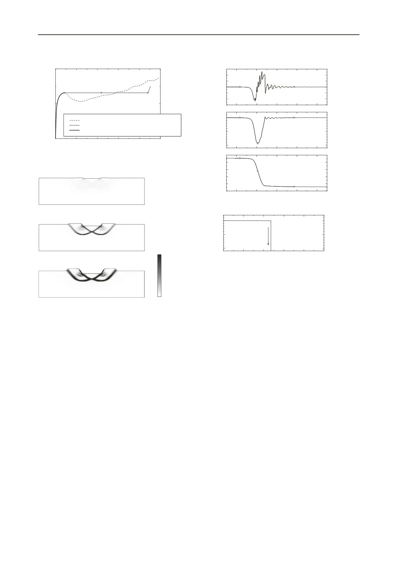
(a)
(b)
(c)
Figure 4. Relationship between vertical load and settlement (load
controlled case)
(a) Commencement of accelerated motion
(just prior to failure)
(b) During accelerated motion
(during failure)
(c) Cessation of accelerated motion
(immediately after failure)
(A) With inertial term
Figure 5.
Shear strain distributions (load controlled case)
simulation resulting in partial failure. However, the velocity
increase is more sudden than in the simulation accounting for
the inertia term and dissipates instantaneously, precluding
further calculation. The velocity change calculated using the
approach accounting for the inertia term results in a maximum
acceleration on the order of 0.25g, much more moderate than
that predicted in the quasi-static analysis. Naturally, this is
because the inertial force resists changes in motion. The
upheaval of ground on both sides of the foundation after failure
can be confirmed in Figure 5. In finite deformation analysis, it
can be imagined that this upheaval plays a significant role in the
transition from accelerated motion to static motion.
Next, comparing the results of the displacement and load
controlled cases in Figure 4, we see that the behavior predicted
is the same up to the point of peak load (a) for the displacement
controlled case. We understand the accelerated motion observed
in the load controlled case occurring after achieving the peak
load in the displacement controlled case as resulting from
external forces that cannot be accounted for statically. If we
change our perspective to that of an observer moving with the
foundation, the inertial force can be said to be an apparent force
that compensates for the deficit in the equilibrium of forces.
Whereas the behavior predicted in the load controlled case
coincides with that for the displacement controlled case up to
the initiation of accelerated motion at point (a), it can be seen
that the behavior at the conclusion of accelerated motion (point
(c)) is not consistent with the relationship between load and
settlement predicted in the displacement controlled case. This is
because the soil elements undergo a different stress history in
-300
-200
-100
0
100
200
300
Acceleration (cm/sec
2
)
(a)
(b)
(c)
0
50
100
Velocity (cm/sec)
(c)
(b)
(a)
8754 8756 8758 8760 8762
0
20
40
60
80
100
Displacement (cm)
Time (sec)
(a)
(b)
(c)
(A) With inertial term
8758 8760 8762 8764 8766 8768
0
50
100
Time (sec)
Velocity (cm/sec)
(%)
s
100
(B) Without inertial term
Figure 6. Time history of acceleration, velocity, and displacement of the
central node of the foundation (load controlled case)
0
failure involving accelerated motion and failure due to static
forces.
4 SIMULATING DELAYED GROUND FAILURE
In order to simulate delayed failure, we increased the vertical
load up to 125, 126, 127, 128, 129, and 130 kPa under the load
controlled condition and then left the load in place. Taking the
discussion in the previous section into consideration, we
performed an analysis using the approach accounting for inertial
force.
The resulting relationship between the vertical load and
settlement is presented in Figure 7 (corresponding to symbols
(a)-(c), (a)’, (a)” in Figures 7 to 10, respectively). It is evident
that there is a significant difference between the settlement for
final loads up to and including 127 kPa and those greater than or
equal to 128 kPa. The relationship between the elapsed time
during a constant load and the displacement velocity in the
central part of the foundation is presented in Figure 8. In the
case of final loads greater than or equal to 128 kPa, similar to
the other cases, the settlement initially and gradually approaches
convergence, but at a certain point the displacement velocity
increases rapidly, after which the settlement again approaches
convergence. The shear strain distribution for the 128 kPa load
after point (c) at which the displacement velocity increases
rapidly is presented in Figure 9. It is evident in the 128 kPa load
case that delayed failure has occurred. As can be seen in Figures
7 and 8, delayed failure occurred for all loads greater to or equal
to 128 kPa. Meanwhile, for all loads up to and including 127
kPa, the consolidation continuously approached convergence.
The existence of a threshold load value above which failure
occurs and below which failure does not occur has long been
verified through experiments on triaxial samples (e.g.
Murayama & Shibata 1956). Up to this point, such phenomena
observed in saturated soils have been treated as a rheologic


