850
Proceedings of the 18
th
International Conference on Soil Mechanics and Geotechnical Engineering, Paris 2013
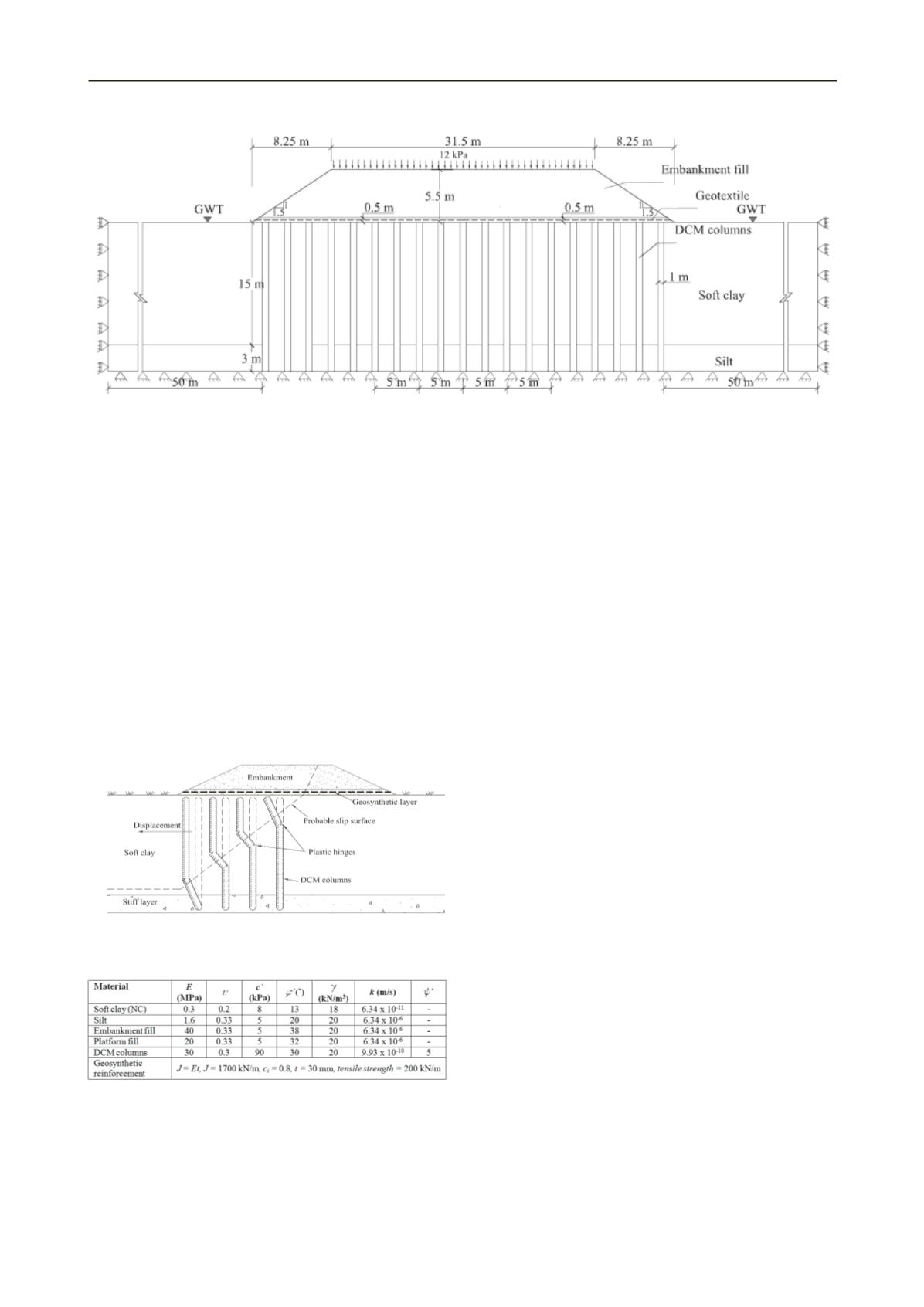
Figure 1.Geometry and boundary conditions for numerical model of the embankment.
The geosynthetic reinforcement is modelled as a linear
elastic perfectly plastic material using the Von-Mises failure
criteria and the embankment fill, platform fill, soft clay, and silt
were modelled as elastic perfectly plastic materials, using the
Mohr-Coulomb failure criteria.
An extended version of the Mohr-Coulomb model is used to
simulate the strain softening behavior of the cement admixed
soil (Yapage et al. 2012). This material extension has been
incorporated into the finite element code, ABAQUS/Standard,
through the user defined field subroutine, USDFLD.
The constitutive model is calibrated using triaxial test data
found in the literature for cement admixed Singapore and Hong
Kong marine clays. The parameters for the strain softening
model in the analysis are peak friction angle,
= 30
,
residual friction angle,
= 13
, peak cohesion,
= 90
,
residual cohesion,
= 70
, peak dilation angle,
= 5
,
residual dilation angle,
= 0
, Plastic deviatoric strain at
peak,
ε
,
= 2%
and at residual,
ε
,
= 12%.
Figure 2. Failure mode of an embankment for internal stability
(Broms 2004).
Table 1. Material properties used in numerical model.
Note:
E
is tangential elastic modulus,
is Poisson’s ratio,
is
the unit weight,
is the effective cohesion intercept,
is the
effective friction angle,
is the permeability,
′
is the effective
dilation angle,
J
is the tensile stiffness of the geosynthetic,
t
is
the thickness of the geosynthetic layer,
i
is the interaction
coefficient between geosynthetic and platform fills
3 IDENTIFICATION OF FAILURE MODES USING FEM
Various instability criteria to identify the failure state during
numerical analysis can be found in the literature: (i) Abrupt
increase in nodal displacements or deformations at a certain
location of the embankment, (ii) Initiation, development and
distribution of plastic strain, shear strain or yielded material
zone in a particular location and (iii) Non-convergence state
within a user-defined maximum number of iterations for the
solution. In this research first and second criterion are used to
identify the failure mechanisms.
4 FAILURE MODES ASSOCIATED WITH
EMBANKMENTS SUPPORTED OVER DEEP CEMENT
MIXED COLUMNS
4.1 Combination of bending and shear failure modes
In this study, it is found that the bending failure and subsequent
slip surface shear failure are critical for internal stability of
GRCS embankments. Broms (2004) illustrated the probable slip
surface for columns located in the active zone as shown in
Figure 2. Therefore, the analysis is carried out considering the
full cross section of the embankment giving allowance to
develop an asymmetric slip surface.
The plastic hinge formation within the finite element model
is shown in Figure 3. When the shear strain development with
gradual loading is investigated, higher shear strains initially
develop closer to the top of the columns at the center of the
embankment and then they progressively develop towards the
bottom of the columns closer to the embankment toe. During
this process, DCM columns fail one by one due to bending
failure. When the maximum bending moments within the
columns exceed the moment carrying capacity of columns,
plastic hinges will develop at these locations as illustrated in
Figure 3. The soft soil in between these columns experience
considerable shear distortions due to abrupt deformation of
damaged columns. The resulting slip surface is not circular and
it is a slip band with a certain thickness as shown in Figure 3.
Columns closer to the embankment toe have a single plastic
hinge, while the middle columns have two plastic hinges with
approximately same distance in between them. When there are
two plastic hinges developed in the column, one should be at the
location of the maximum positive bending moment and the
other one should be at the location of the maximum negative
bending moment. It can be observed that this failure mechanism
agrees well with the critical slip surface given by Broms (2004)
shown in Figure 2.


