854
Proceedings of the 18
th
International Conference on Soil Mechanics and Geotechnical Engineering, Paris 2013
3 EXAMPLES OF DYNAMIC FORMULATION
3.1
Wave propagation in a blasting problem
The dynamic formulation of the MPM is useful to study some
geotechnical problems such as the determination of stress and
deformation in the vicinity of a blasting.
In the case analyzed the detonation is applied in a fractured
granite rock mass, which is covered by a more superficial layer
of sand 5m thick. Both materials have been modeled using a
Mohr-Coulomb constitutive law (see parameters in Table 1)
which has been obtained from a linear approximation of the
rock failure Hoek-Brown criterion at a mean stress of 2MPa.
The problem is three-dimensional and, taking into account
two planes of symmetry, a cubic geometry is modeled (see Fig.
2). The blasting is simulated by means of a horizontal pressure
acting on a borehole 8 m long on one of the edges as shown in
Figure 2. This pressure is applied as a triangular ramp loading
during 0.034 seconds, with a maximum of 2.5 GPa at 0.017
seconds. The mesh was made denser in the vicinity of the
borehole.
Table 1. General characteristics of the granite rock and the sand.
Material parameter
granite
sand
Specific weight γ (kN/m
3
)
25
23
Young modulus E (MPa)
10000
100
Poisson ratio ν
0.33
0.33
Cohesion
c
(
kPa
)
600
50
Frictional angle φ (º)
42
35
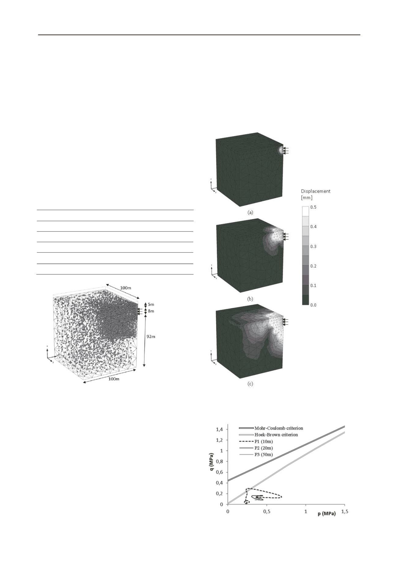
Figure 2. Simulation scheme, dimensions and initial
discretization of the blasting problem.
The rapid application of the load generates a wave which
extends in all directions throughout the domain. The speed of
the wave propagation depends on the Young modulus and the
specific weight of each material: 250m/s in the upper sand and
2500m/s in the granitic rock.
The evolution of the calculated displacement field is
presented in the Figure 3. The maximum displacements are
concentrated in the area of the blasting and they are of the order
of 10
-4
m. The larger the affected area the lower is the
displacement amplitude of the wave front.
Figure 4 presents the stress paths for three points (P1, P2 and
P3) located at a depth of 20m and at distances of 10, 20 and
50m respectively from the origin of the blast. The Hoek-Brown
rock failure criterion with the corresponding parameters of the
granite is also represented in the figure. Only P1 reaches the
Hoek-Brown failure criterion.
3.2
Oedometric consolidation
Consider the consolidation of a soil defined in Table 2. The
sample is a 1m long column, in which traction of 1 kPa was
applied and maintained at the upper boundary. The bottom is
impervious.
The aim of this example is to show the difference between
the (static) Terzaghi analytical expression, and the dynamic
solution, calculated via the MPM code. Moreover, the effects of
damping in the dynamic solution has been analyzed.
Figure 3. Displacements produced by the pressure wave
propagation at different times after the blasting: (a) 0,01s; (b)
0,03s; (c) 0,06s.
Figure 4. Stress paths in the p-q plane for points P1, P2 and P3.


