851
Technical Committee 103 /
Comité technique 103
The bending failure mode mainly depends on the tensile
strength of DCM columns. According to Figure 4, axial loads
acting on columns induce compressive stresses within the
column cross section, while the moment load induces both
compressive and tensile stresses. Therefore, stress distribution
within the column cross section may experience tensile stresses,
depending on the magnitude of bending and axial stresses acting
on columns. DCM columns fail when the resultant tensile stress
exceeds the tensile strength of columns.
Figure 3. Deformed shape of the finite element model.
According to Broms (2004), the tensile strength of DCM
columns are typically 10 to 20% of the unconfined compressive
strength. However EuroSoilStab (2002) recommended that the
columns created by dry method should not be subjected to
tensile stresses due to the uncertainty in the tensile strength of
DCM columns. Navin (2005) also recommended that the
columns should be designed to satisfy the zero tensile stress
condition at any point across the column cross section.
Figure 4. Induced stress distribution in DCM columns.
To avoid negative stress conditions;
+
> 0
1
and
can be defined as follows.
=
4⁄
2
=
=
=
32⁄
3
where
R
i
is vertical load and
M
i
is resultant moment applied on
columns.
The bending strength or the resistance against bending is
mainly governed by the tensile strength of DCM columns.
Numerical results show that the axial load is low for the
columns closer to the toe of the embankment compared to
middle columns. Therefore bending failure of columns is likely
to initiate closer to the toe of the embankment. The geosynthetic
reinforcement provides a resisting moment against the moment
induced by the lateral earth pressure to reduce the tensile stress
developed within the columns. Therefore, the geosynthetic
reinforcement plays a significant role in resisting the bending
failure of columns. Additionally, closer column spacing, larger
diameter columns, or reinforcing the columns with steel bars or
cages, can be used to withstand the tensile stresses developed
within the DCM columns and thereby to protect columns
against bending failure (Wong and Muttuvel 2011).
Kitazume (2008) proposed a simple stability calculation to
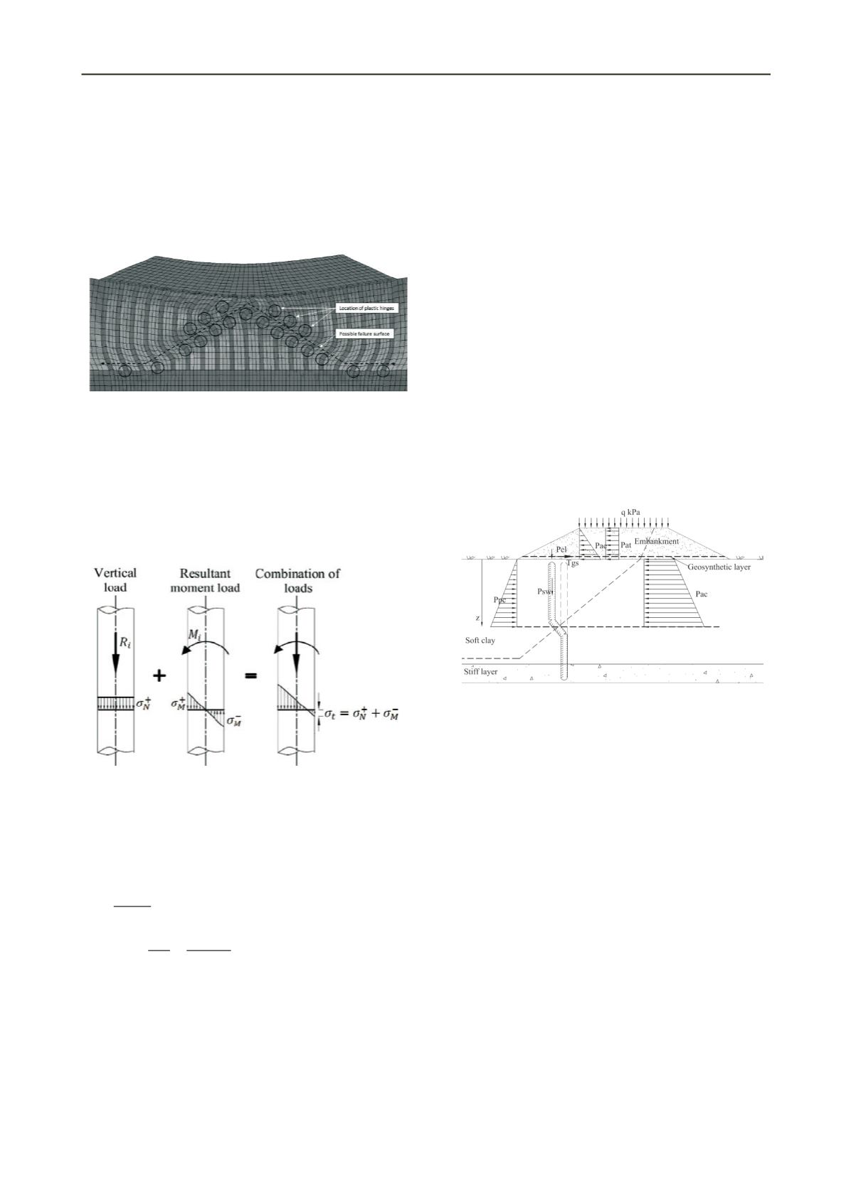
assess embankments over improved grounds against ultimate
bending failure. However, he has not considered the traffic load
over the crest and the tension developed within the geosynthetic
layer. He assumed that the envelope of failure plane of columns
is horizontal. However, the failure plane is an inclined plane as
shown in Figure 3. Therefore, a new stability equation should be
developed against the bending failure considering the inclined
slip surface. In that equation, the active earth pressure due to the
embankment load,
P
ae
,
soft clay,
P
ac
,
and the traffic load,
P
at
,
should be considered as shown in Figure 5 to calculate the
driving moment. Resisting moment should consist of the
contributions from passive earth pressure of the soft clay,
P
pc
,
embankment and traffic load over the columns,
P
el
, self-weight
of columns,
P
sw
, tension in the geosynthetic,
T
gs
, the skin
friction mobilized along the surface of columns and the shear
strength of clay between columns as shown in Figure 5. The
resultant of driving and resisting moments due to loads applied
on columns should not exceed the bending strength of DCM
columns.
Figure 5. Load distribution over columns for embankment in
consideration for the bending failure analysis.
It is important to determine how the gradient of this failure
line varies with geometry and material properties of the
embankment. To achieve this, a detailed parametric study needs
to be carried out before developing analytical equations for the
stability calculation against bending failure.
4.2 Punching failure of fill layers
It is important to investigate the failure modes related to
embankment fill layers such as punching, slip circle or lateral
spreading. However, only punching failure is discussed in this
paper.
The punching failure can be categorized into two types:
local punching failure and overall punching failure. When
column heads are considered, the clay in between columns
settles more than the columns. Therefore, it is possible for
column heads to penetrate into the fill layers, which is known as
the local punching shear failure. If overall punching shear
failure occurs, it is clearly visible at the crest of the
embankment, developing an irregular surface with “humps” at
the column locations and “depressions” in between columns.
Punching failure can be identified from the excessive shear
strains above the columns, and excessive differential settlements
at the base of the embankment in numerical modelling.
To identify these failure modes, two different numerical
analyses were carried out with two different embankment height


