2102
Proceedings of the 18
th
International Conference on Soil Mechanics and Geotechnical Engineering, Paris 2013
th
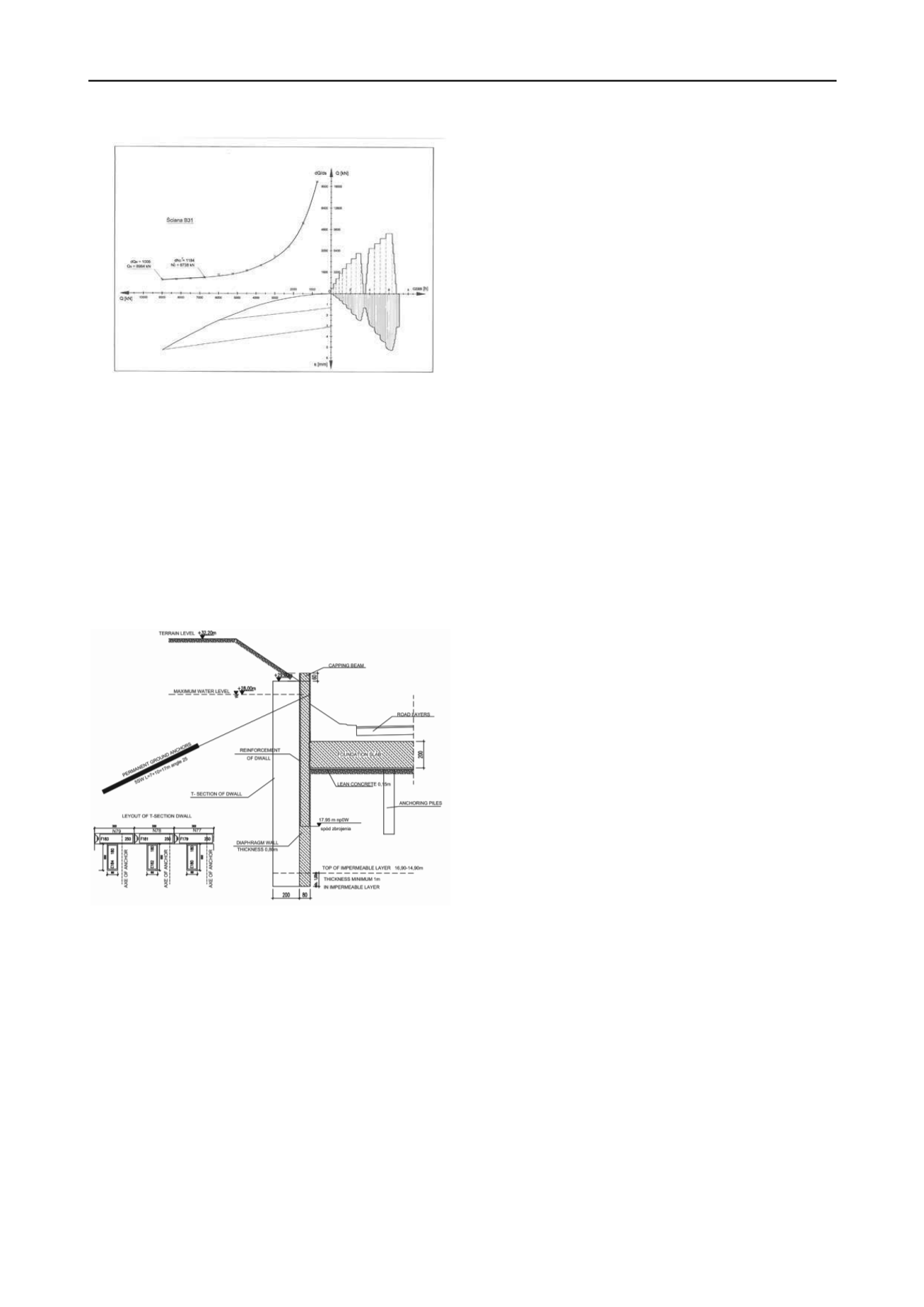
Fig. 5 Static load test result
5 DIAPHRAGM WALLS AS VIADUCT ABUTMENTS
The contour of the casing of the lowest level of the junction
contained 4 viaduct abutments (viaduct W1 and W2). They
were designed as 80 cm thick T-shaped diaphragm walls.
Additional limitations were imposed for these fragments of
diaphragm walls with respect to both horizontal and vertical
displacements, caused by the selection of appropriate bearings.
Additional permanent anchors were implemented – fig. 6, in
order to minimize horizontal displacements of walls. In total, in
the area of viaduct abutments, 31 permanent ground anchors of
the 700kN capacity, were erected.
e code: PN-EN 1537 Execution of special geotechnical works.
etical
no
ding tests made for the barrettes
co
l road junction
construction. Most of the savings were obtained as a result of
significant shortening of construction works.
N-83/B-02482 Foundations. Bearing capacity of piles and piles
foundations.
Ground anchors.
6 SUMMARY AND CONCLUSIONS
The results of diapragm walls (as retaining walls) horizontal
displacements measurements confirmed the correctness of static
analysis of walls and prediction of their displacements, both
made during design stage. Maximum value of horizontal
displacement reached 10 mm for an 80 cm thick wall, anchored
with permanent anchors and it didn’t exceed neither theor
r permissible values. In the case of all other cross-sections,
displacements were smaller and reached up only to 8 mm.
The results of vertical loa
nfirmed the value of calculated theoretical bearing capacity
being 7600 kN to be correct.
There were no significant horizontal displacements of T-
shaped diphragm walls noted (measured).
The new solution applied in the execution design (replacing
the original one from the building permit design) was correct
and resulted in significant savings due to the use of only one
technology for the foundation and the retaining system
(diaphragm walls) of the entire 3 leve
7 REFERENCES (TNR 8)
Soletanche Polska Sp. z o.o. 2010Design of diaphragm walls for
Łopuszańska-Kleszczowa junction, Warsaw
Soletanche Polska Sp. z o.o. 2010Design of anchors for Łopuszańska-
Kleszczowa junction, Warsaw
Soletanche Polska Sp. z o.o. 2008Design of barrettes for Łopuszańska-
Kleszczowa junction, Bydgoszcz
GEOTECH Sp. z o.o. 2010Getechnical documentation for
Łopuszańska-Kleszczowa junction, Warsaw
PN-EN 1538 Execution of special geotechnical works – Diaphragm
walls.
PN-EN 1537 Execution of special geotechnical works – Ground
anchors.
P
Fig. 6 Typical T-shaped D-wall cross-section for the W2
viaduct abutment.
Due to the fact that abutments were founded in the same stiff
sandy clay layer as remaining barrettes made for the
foundations of pillars, additional, special loading tests were not
carried out for the T-shaped diaphragm walls. Bearing
capacities of T-shaped barrettes were calculated by interpolation
of the results of tests loadings of individual barrettes executed
in the near vicinity of abutments. Additional limitations were
imposed for T-shaped diaphragm walls with respect to
horizontal displacements. In order to comply with limitations
and minimize horizontal displacements of walls additional
permanent anchors were implemented. The design load of
permanent anchors was verified during acceptance tests. Each
anchor was stressed up to 125% of its design load and after
stabilization of creeping it was blocked at 80% of its design
load. There were no excess permanent or elastic strains of
anchor tendoms measured, in accordance with regulations of


