2098
Proceedings of the 18
th
International Conference on Soil Mechanics and Geotechnical Engineering, Paris 2013
1.3
System of secant pile wall
For the same site (see Figure 5) an alternative solution has been
analysed with secant pile retaining wall to secure the excavation
pit (27.65x11.55m) but this time with depth of 6.5m. In this
scenario only two floors are planned to be constructed using a
temporary retaining structure. In the first phase the primary,
(reinforced concrete) piles with diameter of 0.6m and length of
7.5m spaced exactly 1.2m should be executed. In the next phase
the secondary (concrete) piles with the same diameter but
shorter depth of 5.5m are constructed. On the top they are
connected by a beam with dimensions 0.6x0.4m as shown in
Figure 9.
Figure 9. A plan of the secant pile wall in X1-X1 section.
The problem is discretized using three-dimensional finite
element model where the soil profile is identical to the one
described in Table 2. For the spatial discretization volume
elements are used in combination with nonlinear-plastic
material definition for the soil and linear-elastic for the
concrete. The calculation is used to determine the stress-strain
behaviour of the soil-structure interaction system, hence
presented through the total displacement in Figure 10.
Figure 10. Total displacement of the soil-structure system in X1-X1
section.
A maximal earth pressure of 33.7kN/m
2
causes horizontal
displacement of 9.8mm, which have been considered as
acceptable. Furthermore, the diagrams of internal pile quantities
are presented in Figure 11.
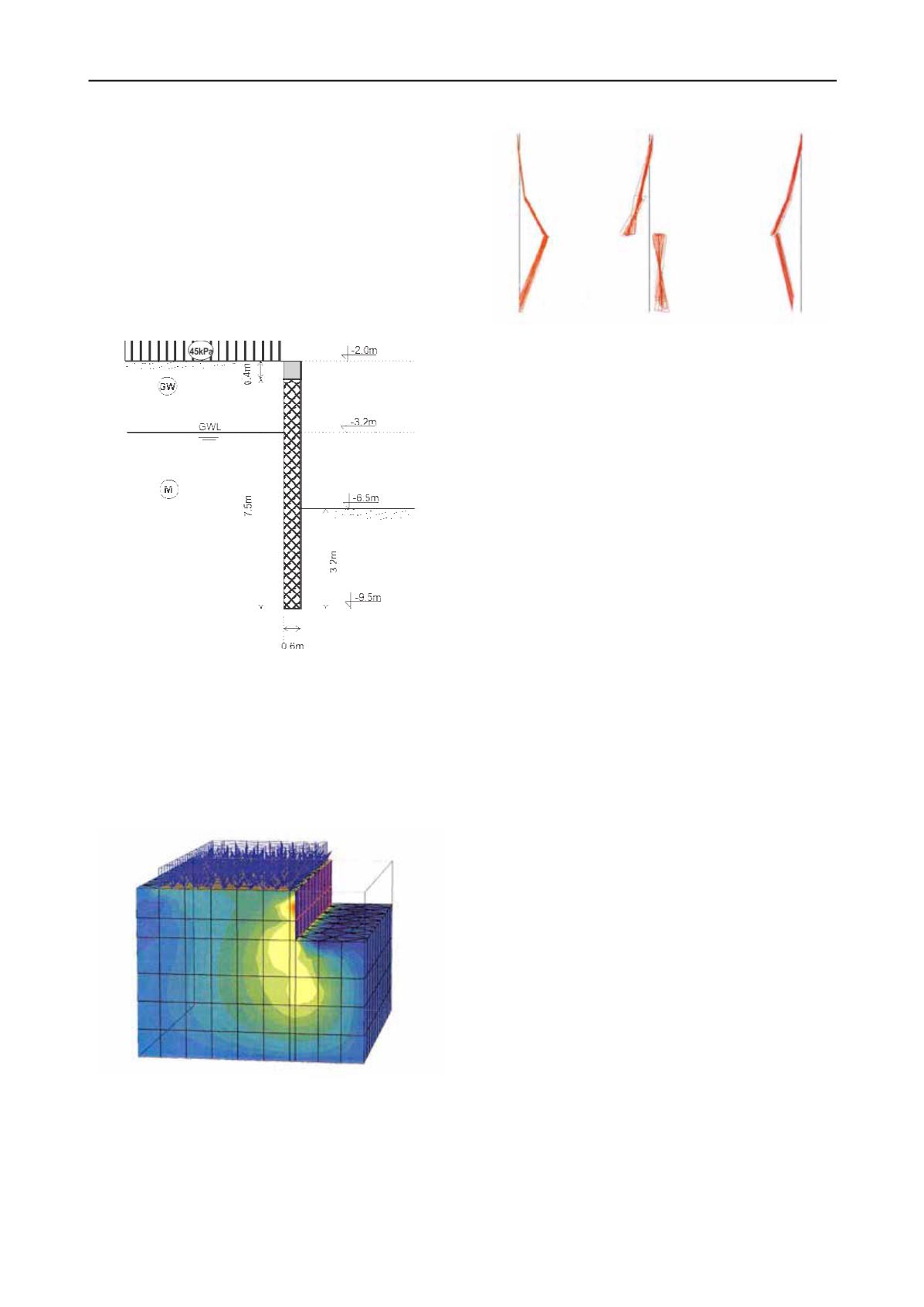
(a)
(b)
(c)
Figure 11. Diagram of (a) Axial force, (b) Shear force and (c) Bending
moments in the pile.
The values of the maximal internal quantities: bending moment
M
=56.81kNm, shear force
Q
=-43.64kN and axial force is
N
=-114.8kN. The pile design has been made using interaction
(M-N) diagrams for C30/37 providing the following
reinforcement: longitudinal 14
ф
16 (28.2cm
2
) and stirrups
ф
8/20cm. Finally, the global stability is controlled where a
safety factor
F
s
=1.55 is obtained.
2 CONCLUSION
The solder H pile wall with lagging is rarely used in our
practice, although it is highly efficient and cost effective for
situations where there is no ground water. Also a greater depth
can be reached when combined with adequate supporting
system e.g. tieback. Nevertheless, in Skopje there are few
locations with low GWL. Although very formidable the systems
with diaphragm wall are seldom used, partially because there is
almost no experience nor there has been clear cost-benefit
analysis. For a long period of time it has been thought that the
costs are very height, which with the present study had proven
not to be the case. Combined with the top-down method of
construction where the wall is permanent structure according to
our analyses remains very cost effective solution. The secant
pile wall technique, in contrast, is very often used in our
practice, sometimes in combination with anchors when greater
depth is needed. It represents formidable solution but usually
takes a lot of the available space and construction time, also
brings high expenses since it is often a temporary structure.
Finally, when comparing all retaining structures we had come to
conclusion that the diaphragm wall represents a preferred
solution for underground construction in highly urbanized
(build-up) areas and situations with high ground water level as it
is usually the case in Skopje.
3 REFERENCES
German Society for Geotechnics (Deutsche Gesellschaft fur
Geotechnike.V.) 2003. Recommendations on Excavations, Ernst &
SohnVerlag fur Architektur und technische Wissenschaften GmbH
& Co. KG, Berlin, ISBN 3-433-01712-3.
Kempfert, H.G. and Gebreselassie, B. 2006. Excavations and
Foundations in Soft Soils, Springer-Verlag Berlin Heidelberg,
ISBN 540-32894-7.
Potts, D.M. and Zdravkovic, L. 2001. Finite element analysis in
geotechnical engineering: application. Imperial College of Science,
Technology and Medicine, Thomas Telford Publishing, Thomas
Telford Ltd, ISBN 0-7277 2753-2.
Moeller G. 2012. Geotechnik. Grunbau, Bauingenieur-Praxis, 2 Ed. Erst
& Sons, A Wiley Company ISBN: 978-3-433-02976-3.
EN 1997-1:1994 Eurocode 7: Geotechnical design - General rules
EN 1538:2000 Execution of special geotechnical works – Diaphragm
walls


