2094
Proceedings of the 18
th
International Conference on Soil Mechanics and Geotechnical Engineering, Paris 2013
of other tests. It is important to note that the points marked by
an asterisk in Figure 6 are largely overestimated, because
approaching the failure the nails underwent to large and
concentrated flexional plastic strains, also for the presence of
rupture wedge of shallow foundation, and, in this strain state the
relationship strain-stress is not linear yet.
Of course the tensile force distributions along nails for all
the tests at failure are similar to those recorded for model
d
,
even if they are not here reported for sake of brevity.
5 FINAL REMARKS
From the experimental results discussed above it is
possible to observe that both flexional and axial stiffness
influence the performance of a soil nailing system in excavation
and at collapse. If the facing has no continuity, its flexional
stiffness can hinder the front deformation during excavation,
thus limiting the mobilization of shear stress along nails. In
addition, if the facing is flexionally deformable but
characterized by low axial deformability, horizontal
displacements of the front too can be controlled. In both of the
cases, at the end of excavation, the system has still a high level
of safety in relation to the global stability problem. On the
contrary, the largest deformations accumulated with excavation
can reduce the safety margin.
6 ACKNOWLEDGEMENTS
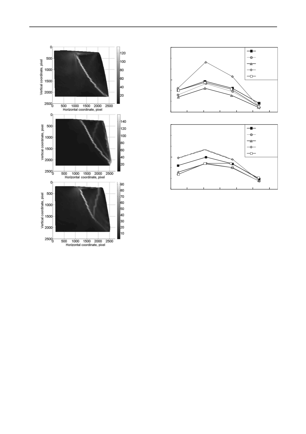
PMMA
MESH
BRASS
NET
PMMA25
0
100
200
300
Distance from facing, mm
0
150
300
Nail tensile force, N
Plate load 5.45 kN - Nail 1
( * )
(* )
We want to thank the Dalla Gassa s.r.l. (Cornedo Vicentino,
Italy), which sponsor this research, and Dr. D.Pilotto and
M.Miuzzi for the valuable help given in the experimental tests.
PMMA
MESH
BRASS
NET
PMMA25
0
100
200
300
Distance from facing, mm
0
150
300
Nail tensile force, N
Plate load 5.45 kN - Nail 2
?
?
Figure 6. Distribution of tensile force along the monitored nails when
the load on plate is equal to 5.45 kN (collapse load of test with NET):
(a) upper nail; (b) lower nail. Notes: 1) the tensile data indicated with
asterisk (*) are determined from strain-gauge readings at a load of 5.30
kN because at greater loads the nails experimented plastic strains in
these positions; 2) The trends indicated with (?) are only presumed, not
measured, due to the detachment of the 2
nd
strain-gauge.
(a)
(b)
(c)
Figure 5. Total shear strain distribution at the face collapse, determined
by mean of PIV in tests with PMMA (
a
), NET (
b
) and PMMA25 (
c
).
7 REFERENCES
Geoguide7, 2008.
Guide to Soil Nail design and construction
.
Geotechnical Engineering Office, Hong Kong.
Gottardi G., Simonini P., 2003. The viscoplastic behaviour of a geogrid-
reinforced model wall.
Geosynthetics International
, 10: 34-46. ISSN:
1072-6349, doi: 10.1680/gein.2003.10.1.34.
EN 14490:2010:
Execution of special geotechnical works — Soil
nailing
.
FHWA-IF-03-017, 2003.
Geotechnical Engineering circular No. 7 –
Soil Nail Walls.
Plumelle C., Schlosser F.
,
Oclage P. and Knochenmus G., 1990. French
national research project on Soil Nailing: CLOUTERRE,
Geotechnical Special Publication ASCE
, 25, 660-675.
Stocker M., 1976. Bodenvernagelung, Vorträge der Baugrundtagung,
Nürnberg,
Deitsche Gesellschaft für Erd- und Grundbau e.v.
, Essen.
White, D.J., Take, W.A. & Bolton, M.D. 2003. Soil deformation
measurement using particle image velocimetry (PIV) and
photogrammetry,
Géotechnique
53(7): 619-631.


