2101
Technical Committee 207 /
Comité technique 207
embedded in these sands. The monitoring of displacements of
the capping beams of diaphragm walls showed that their
maximum value reached 10 mm for an 80 cm thick wall,
anchored with permanent anchors. In the case of other cross-
sections, displacements were smaller and reached up to 8 mm.
No increased displacements of the diaphragm wall were
observed during the process of pile driving.
Design works had to face additional difficulties resulting
from the very complex shape of the facility, involving 4
abutments (T-shaped D-walls, cross-section 6-6) and curved
walls that encased the roundabout (cross–section 5’-5’). Both
the excavation bottom and the top of the walls and the capping
beam were located in slopes. Due to this fact combined with
variable thickness and varied strut methods, almost every single
reinforcing cage of a diaphragm wall was of different type.
Therefore, the contractor who constructed diaphragm walls was
forced to stick strictly to the schedule of execution of particular
sections, without any possibility of introducing changes during
the works.
4 DIAPHRAGM WALLS AS FOUNDATIONS FOR
PILLARS AND COLUMNS
A foundation on barrettes (parts of diaphragm walls) – instead
of large-diameter piles (
120/150) implemented in the
construction design – was designed for 5 supports of the flyover
E1 (4 pillars and 1 abutment) and viaducts pillars – viaducts:
W1 and W2 (fig.1).
The barrettes – as fragments of diaphragm
walls – have a very large base. Therefore, they can transmit
very high loads. For this reason, they are very useful for
structures subjected to very high loads, as in this particular case
of bridge structures.
The replacement, for instance, of the support consisting of
11 piles that were 150 cm in diameter with 6 barrettes resulted
in a considerable acceleration of works, which brought about a
measurable financial result in this particular case. Typical
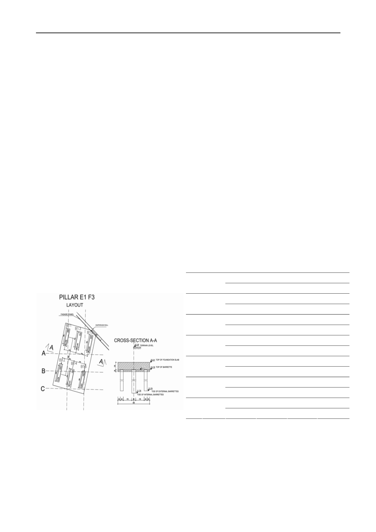
arrangement of the pillar foundation is shown at fig. 4.
Fig.4 Typical pillar foundation arrangement
Barrettes implemented as foundations for pillars had the
following dimensions: 0.6x2.80 m and 0.8x2.8m. They were
from 10.0 to 15.0 m long. They transmitted vertical forces
reaching the max. value of 7600 kN and the bending moment
reaching the max. value of 4996 kNm. In total 44 barrettes were
erected.
Internal forces and moments for each barrette were
calculated using ROBOT software, modelling supports loaded
by a possible most unfavourable load combination. Due to
unsymetrical loading of supports each barrette had different
loading (both - compression as well as tension) and different
bending moments in both directions.
For each of barrettes additional boreholes were made in
order to verify geotechnical conditions. Only then the design of
lengths and calculation of bearing capacities of barrettes were
made. It was considered that barrettes were founded in the stiff
sandy clay layer and the shaft friction was calculated
considering 2 geotechnical layers along barrettes, i.e. stiff sandy
clays and medium dense to dense fine and silty sands.
Base bearing capacities and shaft fricitons were calculated
basing on the regulations of PN-83-B-02482 Foundations.
Bearing capacity of piles and piles foundations.
A base injection system was designed for all barrettes, in
order to ensure as high load-carrying capacity of a barrette as
possible, while ensuring minimum settlements. In each support,
one barrette was selected to be subjected test vertical loads,
supposed to confirm the adapted geotechnical parameters were
correct. The results of test loading showed that the load-carrying
capacity of barrettes was higher than necessary, while the
settlements were smaller than admissible.
Vertical loading tests of barrettes was carried out for 6
barrettes that were gradually loaded up to the maximum of
150% of the calculation force. After reaching 100% of design
load the barrettes were unloaded in order to measure the
resulting permanent settlement. Analogical procedure was used
after reachning 150% calculation force. Permanent settlements
at the 150% force (i.e. 5286 - 10397 kN) did not exceed 4 mm,
while they reached 2 mm for 100% of the calculation force (i.e.
3524 - 6931 kN). The barrette (dimensions: 0.6x2.8m, length:
13.1m) subjected to the greatest load experienced maximum
settlement of 4.35 mm at the load of 10397 kN, where
permanent settlement reached 2.91 mm. The results of
settlement measurements during test loading of barrettes are
compiled in table 1.
Table 1. The results of vertical loading tests of barrettes – settlements.
Settlements for 100%Q
Settlements for 150%Q
No.
Dimens
ions
temporary permanent
temporary permanent
6001 kN
9002 kN
B8
2,8x0,8
x10,0m
3,96mm
1,61mm
7,54 mm
3,53 mm
3524 kN
5286 kN
B12
2,8x0,6
x10,0m
1,33mm
0,75mm
2,82mm
1,71mm
5889 kN
8834 kN
B18
2,8x0,6
x10,0m
2,36mm
1,32mm
4,56mm
2,69mm
5989 kN
8984 kN
B31
2,8x0,6
x12,0m
2,53mm
1,32mm
5,29mm
3,09mm
6931 kN
10397 kN
B24
2,8x0,6
x13,1m
1,99mm
1,08mm
4,35mm
2,91mm
4594 kN
6891 kN
B41
2,8x0,6
x14,0m
1,80mm
1,14mm
4,17mm
2,84mm
As a part of interpretation of the test loading results auxiliary
graphs were ploted as shown at fig. 5, in order to help calculate
the bearing capacity of barrettes.


