2109
Technical Committee 207 /
Comité technique 207
m/s was used in pile walls design (representing mainly leakages
between the piles). Seepage in the foundation pit consists of
wall and bottom rate of seepage. The seepage through the pile
wall on section 1 was 0.008 l/s and can be obtained from
equation
1 3 6
2 2
10x 7.7
2
sm
= d H
t
sk
=w1q
s
(1)
where
H
is the height of the water column,
d
embedding of the wall under the bottom of the foundation
pit.
The predicted flow rate at the pit through walls was 2.12 l/s
in the section farther from Danube and 2.23 l/s in the section
closer to Danube.
Flow rate through the bottom was determined by the relation
Q
b
=
k i A
d
= 0.0567 m
3
/s = 56.7 l/s
(2)
The total rate of seepage can be given as
Q
=
Q
w1
+
Q
w2
+
Q
b
= 61.55 l/s
62 l/s
223 m
3
/h
(3)
In case the groundwater level reaches 138.0 m above sea
level (i.e. level of the pile heads), the rate of seepage in the pit
increases to 266 m
3
/h.
At the beginning of water pumping, static reserve of
groundwater from closed space was pumped from the
foundation pit besides the inflow. The volume of saturated
gravels is 92170 m
3
, of which volume of water by the
assumption of 25 % active porosity is 23043 m
3
. This amount of
water is presumed to be pumped in 9 days (during excavation
works) when pumping more water than 30 l/s over pumped
water flow into the foundation pit.
In order to secure dry foundation pit it was recommended to
modify the length of the piles according to the actual conditions
even though it might result in longer piles in certain sections
compared to the design. Seven pumping wells with diameter
600 mm were proposed with recommendation to verify the
actual pumped amounts. Contractor did not trust the assumption
of the calculation and constructed 10 wells.
During the excavation of the foundation pit, a measuring of
the groundwater movement was performed at all 10 pumping
wells (water was permanently pumped only from 2 wells).
Parameters of groundwater movement were determined by
the single borehole indicator method, based on the principle of
diluting the indicator. NaCl was used as the indicator.
Evaluating NaCl concentration was performed by the Radelkis
OK 104 tool/instrument on battery source, which recorded the
conductivity of the saline solution. Sensors of the Radelkis set
with prolonged cable were used as detectors. The value of filter
speed (
v
f
) in each depth level, as well as the average value for
the whole measured wall, was calculated according to the
relation
pc c
pc oc
tδα
βdπ
=fv
ln
4
(4)
where
d
is the inner diameter of the borehole (
d
= 0.8 m);
- coefficient of drainage impact of the borehole; base on
comparable experience the value
= 2 was used;
- ratio used for volume decreasing (
= 1);
- coefficient considering the sealing impact on the ratio of
flow concentration (
= 1);
t
- time equal to the difference between
c
o
and
c
;
c
o
- initial concentration of the indicator;
c
- concentration in time
t
;
c
p
- background of the indication substance before indicating the
environment.
Average value of filter speed for the test section can be
determined by the relation
i
i
fi
f
Δh
Δh v
=v
(5)
Evaluated filter speed in all measured objects depend on the
location and ground conditions (gravel). No well showed an
anomaly of permeability of depth that would indicate increased
inflows from certain depth level or from the bottom of the
foundation pit. In 2 wells where the water was pumped, filter
speed in the range of 1.4 to 4.7 x 10
-3
m/s was measured, while
in other cases it was
v
f
= 2.2 x 10
-4
to 6.7 x 10
-5
m/s. Very low
seepage ratio was measured in line where jet grouting by the
pile wall was performed, which proves reliability of the sealing
system. Depth division of the filter speeds confirmed non-
homogenity of the gravel location (in some depth the sand
fraction was missing).
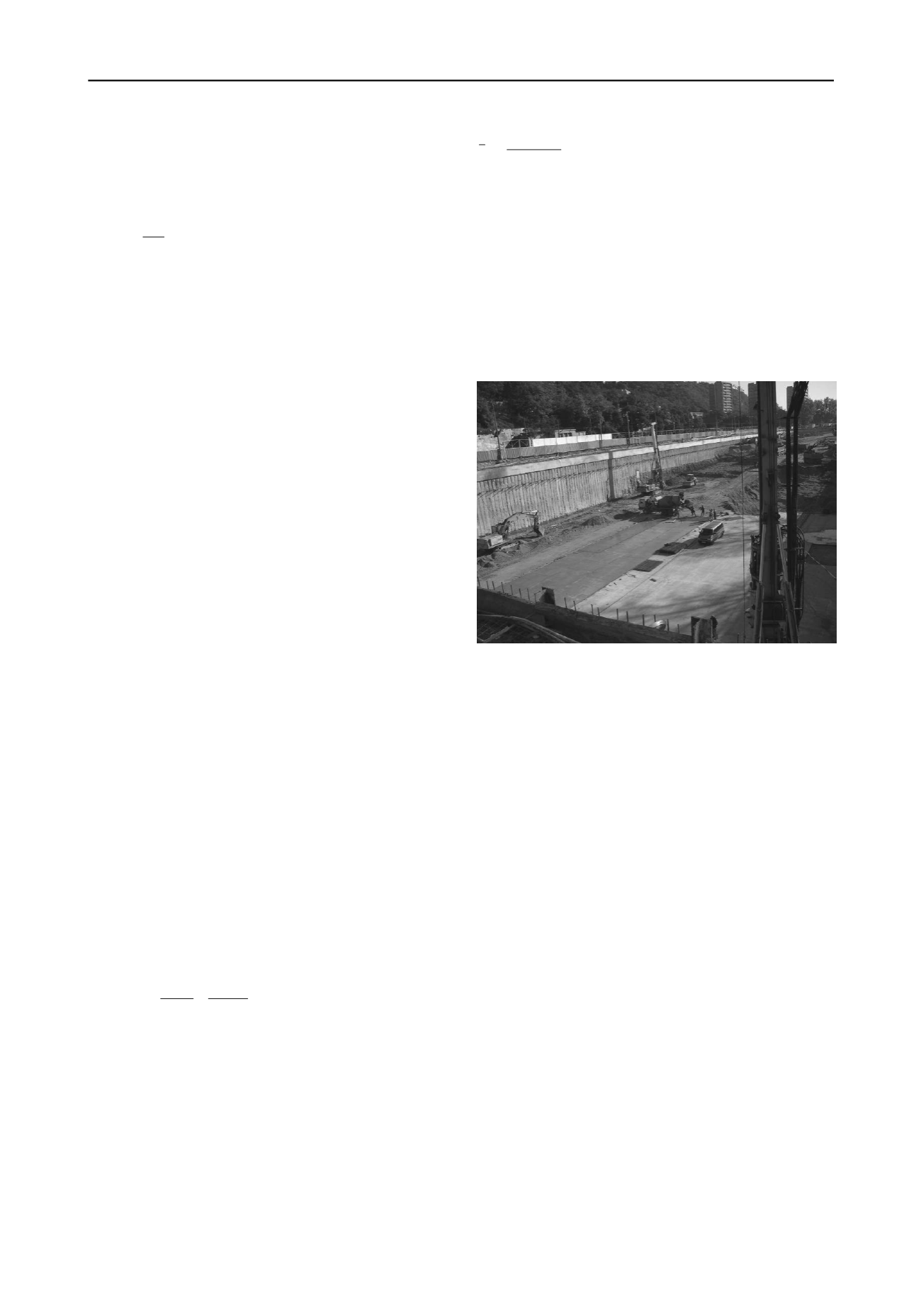
Figure 5. Foundation pit with dimensions of 265 x 53,5 m and depth of
12 m next to Danube river.
Stable pumping at 20 l/s decreased the groundwater head under
the level of excavation base. Decreasing the groundwater head
in the area of the foundation pit and evaluation of the movement
tests by diluting method indicated that lesser amount of water is
required to be pumped from the foundation pit than expected
amount of water in the project design (62 l/s). In conclusion it
was stated that the retaining structure created a foundation pit
with required sealing function.
When preparing the base foundation for placing the
underlying concrete, the excavation in the north-western corner
of the foundation pit deepened for 0.3 m more than was
necessary and minor water seepage occurred along the pile wall
that held at the same level for several days. It was confirmed by
leveling that the groundwater head in the wet area by the pile
wall was 0.48 m bellow the upper edge of the base concrete and
held at the same level. Performed test of natural conductivity of
the water seepage helped in identifying its origin. Two locations
of leakage were confirmed in the wet area along the pile wall. It
was evaluated as the water seepage into the foundation pit area
through the contact of the piles connection in the wall where the
discontinuities in the rock massive were collectors of the water.
Drainage to the nearest active pumping well had to be installed
in order to solve the problem. At the same time it was necessary
to replace existing soil by gravel without the sand fraction in the
foundation pit area and thoroughly compact the layers of this
soil replacement, in order to eliminate the risk of higher
deformations of the future base structure.
4
DEEP EXCAVATION IN PETRZALKA
Quaternary gravel sediments on the right side of Danube were
characterized as loose to medium dense coarse grained soils
with the values of density index
I
D
varying from 0.25 to 0.63


