2100
Proceedings of the 18
th
International Conference on Soil Mechanics and Geotechnical Engineering, Paris 2013
horizontal displacements and settlements were measured and
compared to theoretical values calculated in the design stage.
It has allowed an assessment of the correctness of the solution.
2 GEOTECHNICAL AND HYDROLOGICAL
CONDITIONS
The ground in the land plot consists mainly of Quaternary
formations: river sediments and glaciofluvial deposits as well as
glacial deposits.
In the entire area involved in the investment,
the near-surface layers below man-made fills consist of
medium-dense and dense sands and gravels reaching down to
the max. depth of 18.8 m. Below (the layer roof from 10.6 to -
18.8 m), there are glacial clays, deposited in the form of stiff
sandy clays, clayey sands and, locally, silty clays.
The layer of
anthropogenic soils is not very thick: maximum thickness:
2.2m, average thickness: about 0.5-1.00 m.
Within the entire area, a continuous ground water table was
found in the layer of glaciofluvial sands. The ground water table
was located at about -4.5 m below the ground level.
Occasionally, the water table was confined by lenses of
cohesive soils.
3 DIAPHRAGM WALLS AS A RETAINING WALL
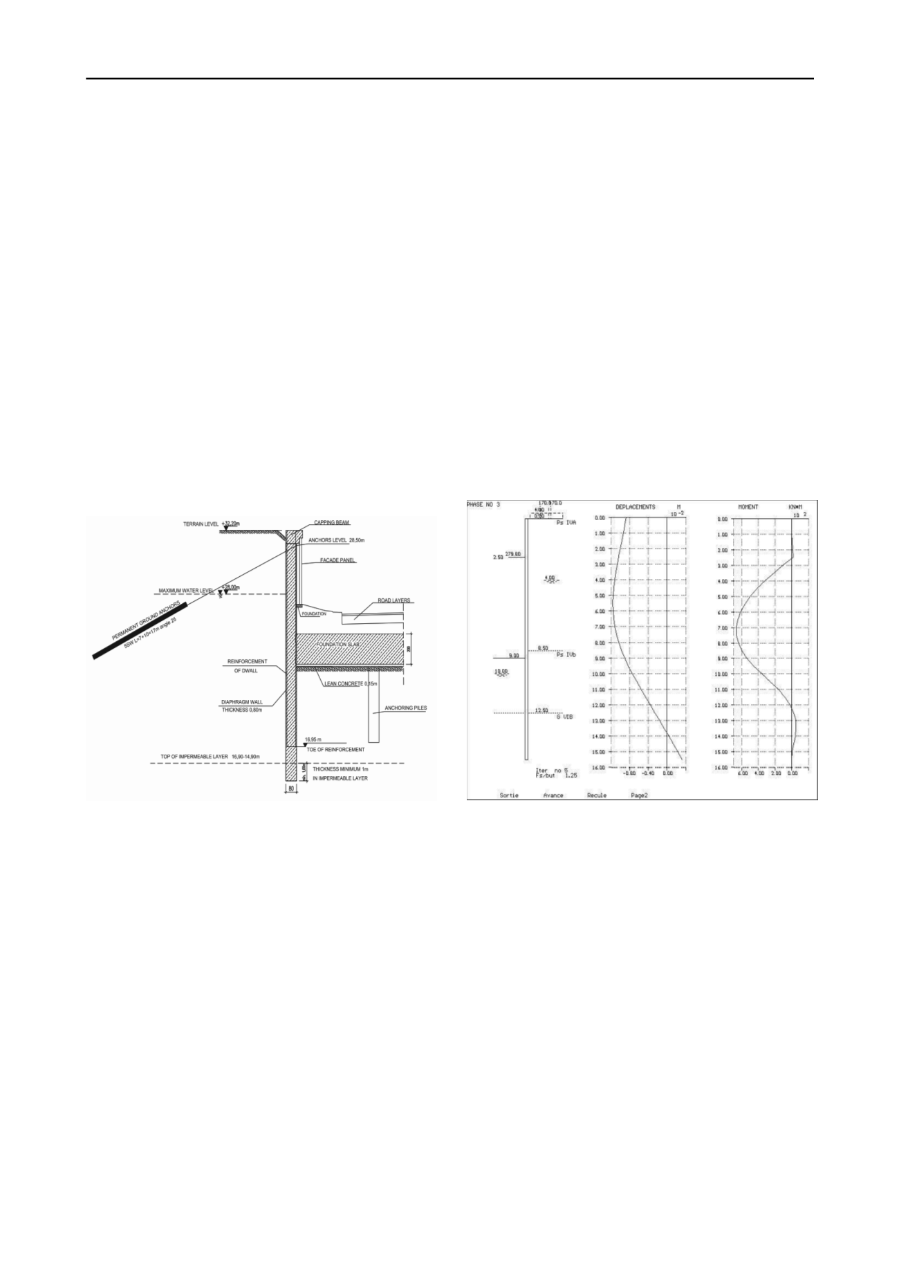
Fig. 2 Typical cross-section of the excavation wall; 80cm thick
diaphragm walls, anchored using permanent anchors.
Due to variable embedding of the excavation below the ground
level, down to the maximum depth of 10 m below the ground
level, diaphragm walls with 3 different thickness values were
implemented, namely 60 cm, 80 cm and 100 cm. Moreover,
different types of protective measures were implemented to
ensure stability of casing walls, i.e:
-
temporary ground anchors, 600 kN capacity (cross –
section 2-2),
-
permanent ground anchors, 600 - 700 kN capacity
(cross-sections 3-3, 4-4, 5-5),
-
permanent ground anchors in the area of T-shaped D-
walls, 700 kN capacity (cross section 6-6).
Some parts of walls reamined not supported (cantilever
walls) due to the small hight of excavation (cross-section 1-1) or
possible colisions with pile foundations outside the wall (cross-
section 7-7).
In total 148 ground anchors were executed (18 temporary
and 130 permanent) and 31 permanent ground anchors for
abutments.
Diaphragm walls along the entire perimeter of the facility
(including the transversal walls) were embedded at least 1 m
down into the impermeable layer, in order to minimise the
inflow of water into the excavation (fig 2). Due to unbalanced
hydrostatic pressure, the ground slab was anchored with
displacement piles in its central part in the deepest excavation
(fig 2.).
Diaphragm walls were designed to resist loads resulting from
soil pressures and from service loads at the ground surface
generated by vehicles and stored materials, amounting to
q=12,0 kPa in the zone removed by at least 1.5 m from the wall
face, and loads generated by heavy traffic, amounting to q=30
kPa. Additionally, the design considered a load generated with
vehicle K located on the roadway located in close vicinity of the
diaphragm wall, in compliance with standard PN-85/S-10030
Bridges. Loads.
Static analysis of diaphragm walls were made using
dependent pressures method (PAROI). 7 typical calculation
cross-sections were verified. Typical results of calculations –
bending moments and displacements – are shown at fig. 3.
Maximum theoretical values of horizontal wall displacements
are as follows:
- cantilever D-wall - 6 mm;
- D-wall and temporary ground anchors - 15 mm;
- D-wall and permanent ground anchors - 12mm;
- T-shaped D-walls - 8mm.
Corresponding bending moments amount to 180 kNm/m up
to 700 kNm/m.
Fig. 3 Theoretical values of bending moments and horizontal
displacements for 80cm thick D-wall with permanent ground anchors
(corss-section 5-5) in the final construction stage.
Benchmarks for geodesic measurements were located on the
capping beam of diaphragm walls, spaced every 50 m at the
maximum. Measurements were carried out for particular stages
of execution of works on site, at least once every month or more
frequently.
Construction stages were as follows:
-
site preparation, sub-base preparation, construction of
guide walls and D-walls with RC capping beam –
reference measurement,
-
excavation 0,5m below the anchoring level –
measurement 1,
-
execution and stressing of ground anchors –
measurement 2,
-
final excavation – measurement 3,
-
verification of displacemants during the execution of
driven piles – subsequent measurements.
Particular attention was paid to measurements of wall
displacements in the vicinity of works consisting in driving
displacement piles in, in order to anchor the ground slab. In the
view of the presence of a layer of silty sands, designers were
concerned about the impact of dynamic pile driving on the load-
carrying capacity of ground anchors, whose bearing plates are


