2108
Proceedings of the 18
th
International Conference on Soil Mechanics and Geotechnical Engineering, Paris 2013
adjacent to streets and only one short site was open to free
space. This layout requires minimisation of horizontal
deformation of the retaining structure. Furthermore, there was
interest to use all space available on the construction lot, i.e. to
exclude technologies that would interfere with the ground plan
and decrease the usable volume of the underground floors.
In the first section of the foundation pit up to the depth 4.5
m, where dry conditions were expected, the soil nailing was
used as support. The jet grouted wall in deeper section was
anchored by one level of ground anchors 15 m long, with 25°
inclination, the anchor force was 670 kN and spacing of the
anchors 1.6 m. The retaining wall was prestressed in vertical
direction due to the necessity to carry large bending moments
(bending moment of 1332 kNm per meter of wall was expected
by full excavation of the pit); this pre-stressing was supposed to
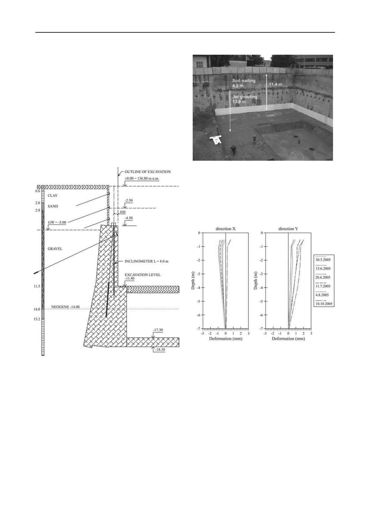
limit the horizontal deformation (see fig. 2 and 3).
Figure 2. Cross section of retaining structure made by soil nailing and
jet grouting.
According to geotechnical investigation the Neogene soils
with high permeability are expected at the excavation base.
Therefore a sealed bottom of the foundation pit was proposed
by overlapping short columns constructed by jet grouting. This
solution proved to positively influence the settlement of the
building. Horizontal deformation in the level of the retaining
wall 3.3 mm and 19.15 mm in the lower embedded part under
the bottom of the excavation (in the direction of the excavation)
were expected in geotechnical design. By full excavation the toe
of retaining wall was expected to move into the foundation pit
by 52.56 mm. Nine inclinometers were installed around the
foundation pit in the wall constructed by jet grouting. The
example of measurements from inclinometer no. 3, where the
highest deformations (not higher than 2 mm in the direction into
the pit) were indicated, is on figure 4.
Figure 3. View into the excavation. Retaining structure made by soil
nailing and jet grouting.
Similar results with even lower deformations were measured
by other inclinometers. This favourable outcome was achieved
thanks to high stiffness of the retaining wall prestressed in
vertical direction. The stiffness of weak sandy clays under the
bottom of excavation has been increased by constructing a
horizontal barrier by jet grouting.
Figure 4. Horizontal deformations of retaining structure during
construction.
3
EXCAVATION FOR RIVER PARK
The second case study is the foundation pit with dimensions of
265x53.5 m and depth of 9.0 m (fig. 5) situated directly at
Danube riverside (in the distance of 12 m to Danube river).
Retaining walls for foundation pit were designed as a secant pile
wall embedded 1m into the weathered rock base. Danube coarse
grained soils are well-known by their susceptibility to piping.
The analysis of the risk of filtration failures is important in
geotechnical design. Risk of the internal erosion (structural
erosion) is affected by granularity of gravel or sand soils,
situated in this region. Therefore the analysis of seepages effect
on safety of construction and its subsoil it is necessary to
carefully observe mainly development of filtration velocities or
hydraulic gradients, which are decisive from the viewpoint of
reviewing filtration stability of soils (Bednárová et al., 2010).
According to geotechnical investigation the value of
permeability coefficient (hydraulic conductivity) of gravel
k
is
in the range from 1.5x10
-2
to 6.5x10
-3
m/s. The characteristic
value of
k
equal to 1x10
-5
m/s was evaluated from the results of
water pressure tests. The permeability coefficient
k
= 1x10
-7


