2096
Proceedings of the 18
th
International Conference on Soil Mechanics and Geotechnical Engineering, Paris 2013
The task has been to secure the pit from only one side (namely
from the frequent street which connects the main city square)
allowing undisturbed traffic and pedestrian communication.
As solution a temporary structure of solder H piles with lagging
has been proposed. The supporting system uses rikers and struts
(positioned on -2.0m and -4.65m from the top) acting upon the
foundation of the existing structure. There were several
arguments in favour of this solution, foremost it is light and
suitable for a temporary structure, does not take a lot of space
and last but not least it is relatively cheap.
Figure 2. Site location No.1 with RW as solders H piles with lagging.
The structure is modular consisted of eighteen solder H piles
placed on every 2m with total length of 7.5m. The piles are
embedded with depth 0.5m. A steel IPE 40 profile has been
chosen according to DIN 1025 B1.5 and DIN 17100
specifications.
The ground profile from 0 to 3m is defined by a layer of fill
with pieces of construction material such as bricks and mortar.
From 3 to 7.5m there is clayly silt with smaller pieces of
construction debris with the following material properties: unit
density as
γ
=19kN/m
3
, cohesion as
c
=5kPa, angle of internal
friction as
φ
=28
0
and Compressibility modulus as
М
v
=8000kPa.
A standard traffic load with
q
=16.67kPa acting on the far away
and
p
=5kPa on the nearby strip has been assumed.
The problem is calculated using the finite element method using
plane and beam element. The structural elements of the wall are
assumed to be linear with smeared stiffness as in equivalent
plane-strain model. The soil is discretized by Mohr-Coulomb
material behaviour. A plot of the total displacements is shown
in the Figure 3.
Figure 3. Shading plot of the total displacements.
The maximal total displacement is 64mm registered in the toe of
the wall while on the top(-surface) it is around 10 times smaller.
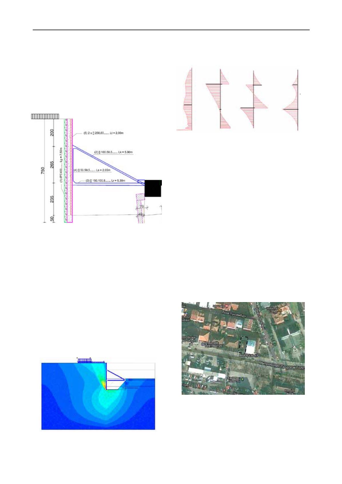
The results of the analysis of solder H pile wall are presented in
the Figure 4.
(a)
(b)
(c)
(d)
Figure 4. Diagram of (a) Active earth pressure, (b) Axial force,
(c) Shear force and (d) Bending moment.
The steel cross sections are calculated according to the
provisions in EC3 with
γ
S
=1.15. A steel type „Fe235“ with
allowable stress of 204MPa has been used.
The rickers prop the wall at -2.0m and are positioned at angle of
23.5 degrees with length of
L
k
=6.65m. They are designed as a
rectangular hollow section []100.50.5. The struts prop the wall
at -4.65m with length of
L
r
=6.1m. They are designed to accept
compression force using rectangular hallow section []150.100.5.
Last but not least, the wooden lagging (
b
=25cm,
l
=182cm and
t
=12cm) are positioned over the height of 7m between the
soldier piles.
Finally, the global stability is controlled using the so-called
phi
-
c
reduction procedure. A global factor of safety
F
s
=1.37 has
been obtained which is larger than 1.1 as recommended value
for temporary structure.
1.2
Top to down construction of system with diaphragm wall
Following the site conditions (see Figure 5) a building with five
underground floors with depth of -15.86m should be
constructed. From two sides there are existing buildings, one of
which is adjacent on six floors and one basement while the
other one is 3m away with only two floors and shallow
basement. From the third side there is very frequent boulevard
which leads to the centre and main city square.
Figure 5. Site location No.2 on M.T. Gologanov boulevard.
The base dimension of the excavated pit are 27.65x11.55mn not
very large around 320m
2
, but due to the difficult surrounding
conditions and the great depth it has been decided to use the top
to down approach of construction. The diaphragm wall is
considered to be a permanent structural element, which in the
first phase carries the horizontal (earth) pressure loads while in
exploitation it will be responsible also for the loads form the
superstructure. Following the top-down procedure the
diaphragm will be supported by the previously constructed RC
27.65m
11.55m
35kPa
50kN
5kN
85kN
50kN
-165kNm
-32kNm
-7.8kNm
q(kPa)


