2097
Technical Committee 207 /
Comité technique 207
slabs, thus enabling the further excavation of the pit. The
excavation process and slab support construction is described in
Table 1 with respect to the depth
h
.
Table 1. Excavation phases
Phase 1
2
3
4
5
6
7
h
(m) 0.0
-3.5
-6.11 -8.5
-10.9 -13.9 -15.8
The diaphragm RC segments are 2.5m long and 0.4m width
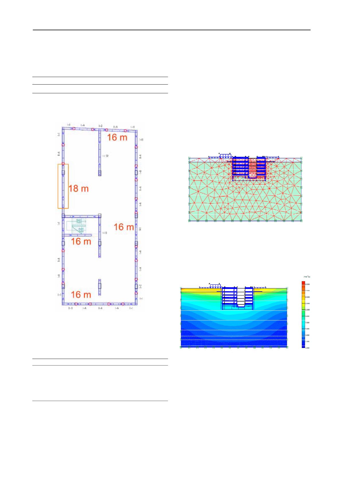
organized as primary and secondary. The base plan with depth
and sequence of construction is presented in Figure 6.
Figure 6. Base plan of primary and secondary diaphragm segments.
The depth is 16m only in one section its 18m due to the
requirement necessary for elevator equipment. The soil profile
is established through set of field and laboratory investigations
which were used to define the material properties given Table 2.
Table 2. Soil properties
Type
h
(m)
γ
(kN/m
3
)
ν
(/)
M
v
(MPa)
c
(kPa)
φ
(
0
)
N
-1.0
17.0
0.30
3
5
18
GW
-3.5
19.0
0.32
30
0
32
M
-4.0
22.0
0.27
35
100
30
M
-10.0 24.0
0.26
45
150
32
M
-20.0 24.0
0.26
55
200
34
where
γ
is a unit weight,
ν
is a Poisson’s ratio,
M
v
is
Compression modulus,
c
is cohesion and
φ
is angle of internal
friction. They are given for every lithological unit: top layer (N)
is a man-made embankment brownish silty clay containing
pieces of bricks and roots with a thickness of 1m, followed by
layer (GW) is sandy gravel with thickness of 2.5m to 3.7m;
continuing as a layers (M) which are Neogene’s deposits
composed by claylike Marls to highly weathered alveoli. The
underground water is detected at -3.2m below ground surface in
layers (GW) while the bottom layers are with low permeability
and relatively dry.
In order to obtain more realistic behaviour of the deep
excavation process secured by diaphragm wall, the problem has
been analyzed using the finite element method. The ground
stress-strain state during excavation is determined through a
plane-strain finite element model. The soil is discretized as
elasto-plastic material using a Mohr-Coulomb definition vis-a-
vis the reinforced concrete wall as a linear material. The spatial
discretization had been varied depending on the situation and
detailing level but in general triangular plane elements with 15
nodes had been used. Two cross sections both in X-X and Y-Y
direction had been discretized and calculated. The structural
elements were modelled using three node beam elements, see
Figure 7.
Figure 7. Finite element model of X1-X1 section.
The underground structure has been calculated for two loading
combinations, namely the construction loading situation with pit
excavation (in 6 phases = 1-diaphragm wall + 5-floor slabs) and
exploitation situation (with permanent + temporary + seismic
loads). In Figure 8 the total displacements of underground
structure is presented for the second loading combination.
Figure 8. Total displacement of the soil-structure system in X1-X1
section.
The maximal registered displacement is 14mm with
predominantly horizontal component (stiff rocking response)
due to the seismic loading. According to the stress-strain
distribution the internal quantities of the structural elements had
been determined. They were used for structural design of
elements such as, diaphragm wall, floor slabs and foundation
plate. The reinforcement is determined according the EC2 for
C35/45 and S500 (with
γ
C
=1.5 and
γ
S
=1.15). The reinforcement
of the diaphragm wall is around 0.8%A
c
(area of concrete
section). The 47% of the total reinforcement will be used for the
diaphragm wall, 18% for the foundation plate and 35% for the
floor slabs.


