2958
Proceedings of the 18
th
International Conference on Soil Mechanics and Geotechnical Engineering, Paris 2013
methods have been designed to install the XCC pile (Liu
et al
.
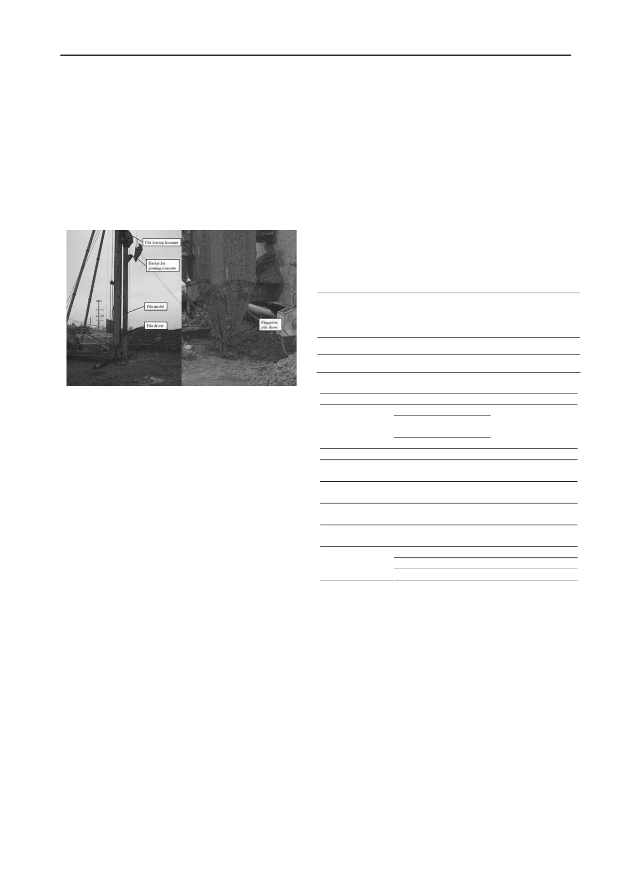
2007). Pictures of the piling machine in action and the flap pile
shoe are shown in Fig. 1.
The construction procedures for XCC piles are as follows:
First, the vibratory pile driver is connected to the X-section steel
casing by flange. Next, the X-section steel casing is connected
with the flap pile shoe. Then, the vibratory driver drives the X-
cross section steel casing into the desired elevation. After
reaching the required penetration depth, concrete is then fed
through the X-section steel casing inlet mouth. Finally, use the
vibrating driver to extract the casing to the ground. Thus, XCC
pile is formed. Pile cap can be constructed after casing is
removed.
Figure 1. Physical diagrams of pile-driving machine: (a) XCC pile-
driving equipment and pile mould; and (b) Pile driver locating and
flappable pile shoes.
3 QUALITY ASSURANCE AND QUALITY CHECK
In order to improve the quality of pile, the withdrawing rate
should be controlled within 1.0 to 1.5 m/min under normal
circumstances. The casing should vibrate for 10 s before
withdrawal. Subsequently for every 1 m withdrawal, the pulling
should be stopped temporarily to vibrate the casing for 5 to 10 s
until the casing is completely withdrawn. The vibratory effect
applied to the casing during withdrawing also helps the concrete
to be compacted. The maximum depth of the XCC pile is
controlled by the height of the XCC piling machine and is
normally within 25 m, and too long pile casing will reduce the
install speed. The maximum advantages of XCC pile is the
contact areas of pile-soil interface improvement with special
cross-section. The most difficult part of XCC pile construction
is the shape of pile head, overflow concrete may change the
shape as the lateral soil pressures near ground are low.
To check the quality of the pile after formation, the
following four methods can be used: (1) excavate the
surrounding soil of pile to check the shape of piles, (2) static
pile load testing, (3) low-strain integrity testing, and (4) amount
of concrete poured in during concreting. To excavate the
surrounding soil of pile for visual inspection and for taking
concrete samples from the XCC pile is a good way to check the
quality of XCC pile. Obviously, static pile load testing, and
low-strain integrity testing can be also used for XCC pile.
4 LARGE-SCALE MODEL TEST
4.1 Summary of Model Test Conditions
A large -scale test facility is composed of a fairly rigid model
container, a loading system, and a data measuring system. The
model container is measured as 5 m × 4 m × 7 m (length ×
width × height). The loading system consists of hydraulic jacks,
beams, reaction walls, and hanging baskets and bolts, etc. The
data measuring system consists of load cells, reinforcement
bars, earth pressure cells, frequency instrument device, and
LVDTs.
The soils used to fill the model container consist of both
sand and clay, taken from Hexi District of Nanjing, China. The
sand is uniformly graded with uniformity coefficient (
C
u
) and
curvature coefficient (
C
c
) equal to 1.58 and 0.99, respectively.
The soil layers are filled in the container by controlling the
density of the in-place dry soils. The dry density for sand and
clay is 1.54 ~ 1.57 g/cm
3
and 1.47 ~ 1.51 g/cm
3
, respectively.
The mechanical properties of the soils with the specified density
are shown in Table 1. The soil layers in the model test container
are as follows: sand of 2.4 m deep at the top, clay of 3.9 m deep
in the middle, and crushed rock of 0.3 m at the bottom.
Two pile types (XCC pile and circular pile) were subjected
to three different modes of loading (axial compression, uplift,
and lateral load) at the top of the pile for deriving load transfer
behavior. The experimental set up is summarized in Table 2.
Table 1. The mechanical indices of test soil with the specified density
Materials Cohesion,
c
(kPa)
Internal
friction
angle,
φ
(°)
Compression
modulus,
E
s
(MPa)
Moisture
content,
ω
(%)
Control
density,
ρ
(g.cm
-3
)
Sand
17.60
25.90
17.00
5.10
1.55
Clay
27.60
21.20
4.60
16.70
1.50
Table 2. Summary of model test conditions
Types
XCC pile
Circular pile
Diameter,
a
(m) 0.530
Distance of arc,
b
(m)
0.110
Section size
Open arc,
θ
(
o
)
90
Diameter,
R
(m)
0.426
Pile length,
L
(m)
5.0
5.0
Cross-section
area,
A
(m
2
)
0.1425
0.1425
Pile perimeter,
C
(m)
1.759
1.338
Pile modulus,
E
(GPa)
28.5
28.5
Moment of
inertia,
I
(cm
4
)
186430.6
161580.0
Compressive
Compressive
Uplift
Uplift
Loading types
Lateral
Lateral
The dimension of XCC pile constructed in the test facility is
as follows: 5.0 m in length (
L
), 0.53 m in the diameter of
outsourcing (
a
), 0.11 m in the spacing of two open arcs (
b
), and
90° in angle of open arc (
θ
).
The reinforcement cage of the
XCC pile is made of four reinforcing bars, with 12 mm in
diameter and 0.35 m in the distance between the opposite
reinforcing bars. The 28-day compressive strength of model pile
concrete is equal to 28.5 GPa (JGJ94). Reinforcement sister
bars were attached to the reinforcing bars, earth pressure cells
were laid on pile tip and the surrounding soils, respectively.
During the load tests, the total load applied to the pile head was
measured by a load cell placed on the pile head, while the axial
force along pile depth was calculated from the attached sister
bars. The soil pressures were measured by the earth pressure
cells, while the settlement of the pile head was recorded by two
LVDTs installed symmetrically at the pile head. Data from the
load cells and LVDTs during the load test were captured by a
data acquisition system.
In order to perform a comparative analysis between the XCC
pile and the circular section pile, a typical circular pile was also
constructed and tested in the test facility. The dimension of the
circular section pile is as follows: 5.0 m in length (
L
) and 0.426
m in diameter (
R
). The cross section area of the circular pile is
equal to 0.1425 m
2
which is the same as that of XCC pile.


