2256
Proceedings of the 18
th
International Conference on Soil Mechanics and Geotechnical Engineering, Paris 2013
Proceedings of the 18
th
International Conference on Soil Mechanics and Geotechnical Engineering, Paris 2013
etermination of the shear strength
arameters at the sliding surface. Two rows of stabilizing piles
ere designed through the sliding mass and the structural
nalyses and also FE analyses of these piles were performed
dependently.
ed concrete piles are placed with 1.25 m spacing
in this row. The pile lengths are 17 m. The total length of the
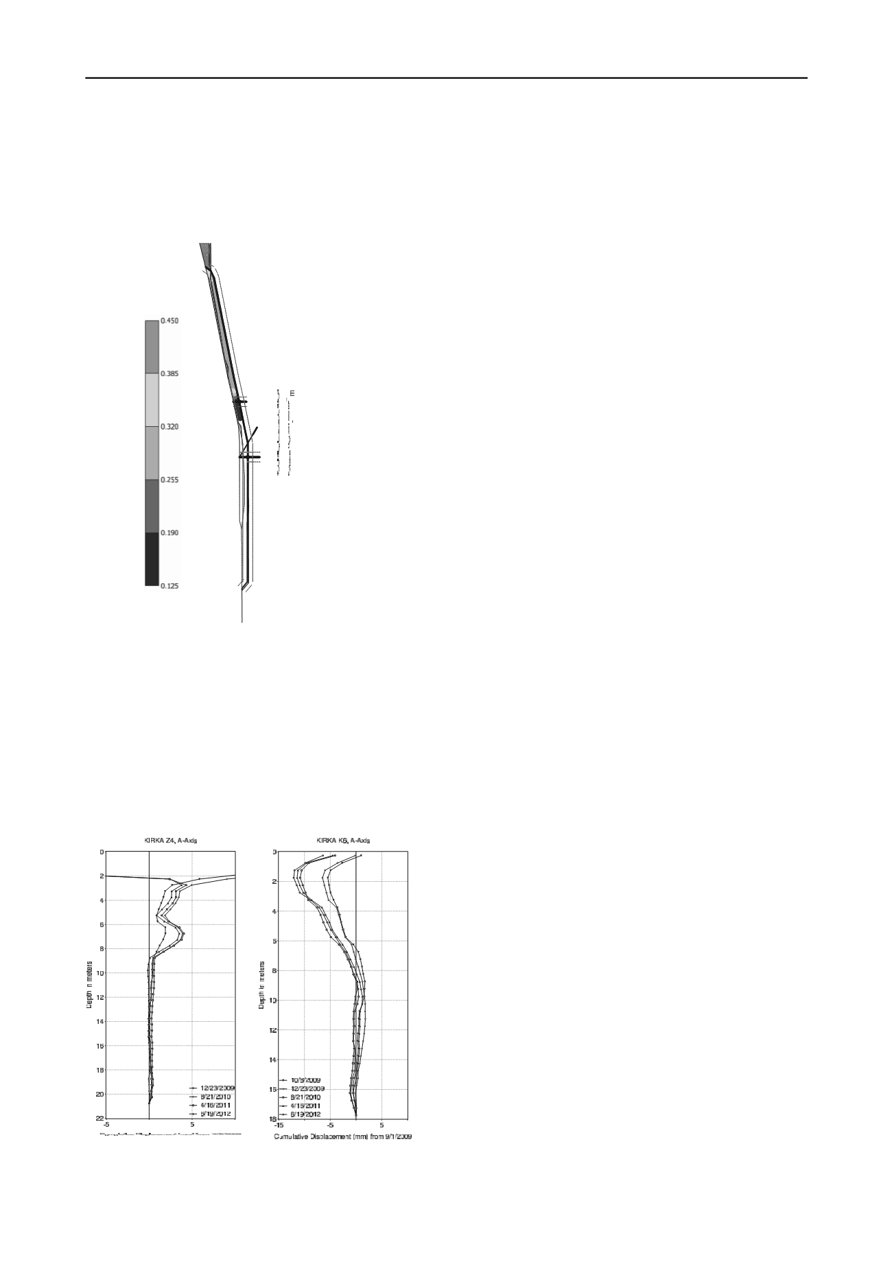
Figure 4. Cumulative displacements (mm) at Z4 (soil) and K6 (pile)
inclinometers
ee to the horizontal.
plastic tuffs. Back analyses and the laboratory tests were
performed for the d
p
w
a
in
Figure 3. Total displacements plot of FE analysis
10 to 15 m deep excavations were performed for the first
stage of the stabilization works. The upper level piles (K1) were
12 m in length and 1.2 m in diameter. Center to center spacing
of piles were 2.5 m. The total number of stabilizing piles is 30
covering a longitudinal length of 72 m reaching the South edge
of the landslide. The 2nd row of stabilizing piles (K2) was also
used as the retaining walls of the facility. The 1.2 m diameter
bored reinforc
pile row is 137 m in plan view passing over the South edge of
the landslide.
The permanent ground anchors were constructed at the head
beam of the piles with 1.25 m spacing, 30 to 35 m in length and
inclined at 30 and 45 degr
No drainage system was planned in the sliding mass. Instead
surface drainage was implemented as reinforced concrete
drainage channels at the edges of the landslide and at the upper
levels of the new road. Behind the retaining walls of the
construction site 0.60 m diameter vertical drainage shaft
between the piles were planned and the collected groundwater
was transferred to the water drainage system of the facility.
The deformations of the system are controlled by the 12
inclinometers (8 in the soil, 4 in the piles) at each stage of the
construction works. There are no displacements in three years
(Figure 4).
4
REFERENCES
Brinch Hansen, J. 1961. The Ultimate Resistance of Rigid Piles against
Transversal Forces.
Bulletin of the Danish Geotechnical Institute
(12).
De Beer, E. 1977. Piles Subjected to Static Lateral Loads.
Proceedings, 9th I.C.S.M.F.E., Specialty Session 10, Tokyo.
Ergun. M.U. (2000), “Stabilization of Landslides using Piles”,
Landslides in Research, Theory and Practice, Proceedings of the
8th International Symposium on Landslides, Vol.1, pp:513-518,
Cardiff, 2000.
Fukuoka, M., "The Effects of Horizontal Loads on Piles due to
Landslides", Proceedings, 9th I.C.S.M.F.E., Specialty Session 10,
Tokyo, 1977
Ito, T. and Matsui, T., "The Effects of Piles in a Row on the Slope
Stability", Proceedings, 9
th
I.C.S.M.F.E., Specialty Session 10,
Tokyo, 1977
Kourkoulis, R. Gelagoti F., Anastasopoulos I, and Gazetas, G. (2012)
Hybrid Method for Analysis and Design of Slope Stabilizing Piles,
Journal of Geotechnical and Geoenvironmental Engineering
,
v138(1), pp:1-14.
Popescu, M.E., "Landslide Control by Means of a Row of
Piles", Slope Stability Engineering, Thomas Telford, pp: 389-
394, London, 1991
Poulos, H. G. (1995). “Design of reinforcing piles to increase slope
stability.”
Can. Geotech. J.,
32(5), 808–818.
Reese, L., Wang, S., and Fouse, J. "Use of Shafts in Stabilizing a
Slope", Slopes and Embankments-II A.S.C.E., Speciality Session,
1992
Sommer, H., "Creeping Slope in a Stiff Clay", Proceedings, 9th
I.C.S.M.F.E., Specialty Session 10, Tokyo, 1977
Viggiani, C., "Ultimate Lateral Load on Piles Used to Stabilize
Landslides", Proceedings, 10th I.C.S.M.F.E., Vol.3, pp: 555-560,
Stockholm, 1981
Winter, H., Schwarz, W. and Gudehus, G., "Stabilization of Clay
Slopes by Piles", Proceedings, 8th European Conference on
S.M.F.E., pp: 545-550, Helsinki, 1983


