2255
Technical Committee 208 /
Comité technique 208
Proceedings of the 18
th
International Conference on Soil Mechanics and Geotechnical Engineering, Paris 2013
eded to
inc
t al. (2012) developed a hybrid solution to
the problem, combining the benefits of accurate 3D finite
element simulation with the simplicity of widely accepted
analytical
removed-see
Fi
completed. Because
of the piles, the
reasing for both
re being related to the undrained cohesion of the soil and
is a limit valu
for s
≥
3d whe
pil
The general design procedure consists of two main steps:
Step 1: Provision of the required total lateral force ne
rease the factor of safety of the slope to the desired value
(based on analysis of the unreinforced slope). Step 2:
Calculation of loading on piles and pile lateral capacity.
In the last few years, 3-dimensional finite-element and finite-
difference methods are becoming increasingly popular. Using
these methods complex geometries and complicated
phenomenon such as soil arching, pile group effects,
nonlinearity of soil and pile could be modeled. Use of 3D
numerical methods is still not very attractive to practitioner
engineers because of the long computational time and learning
effort. Kourkoulis e
techniques.
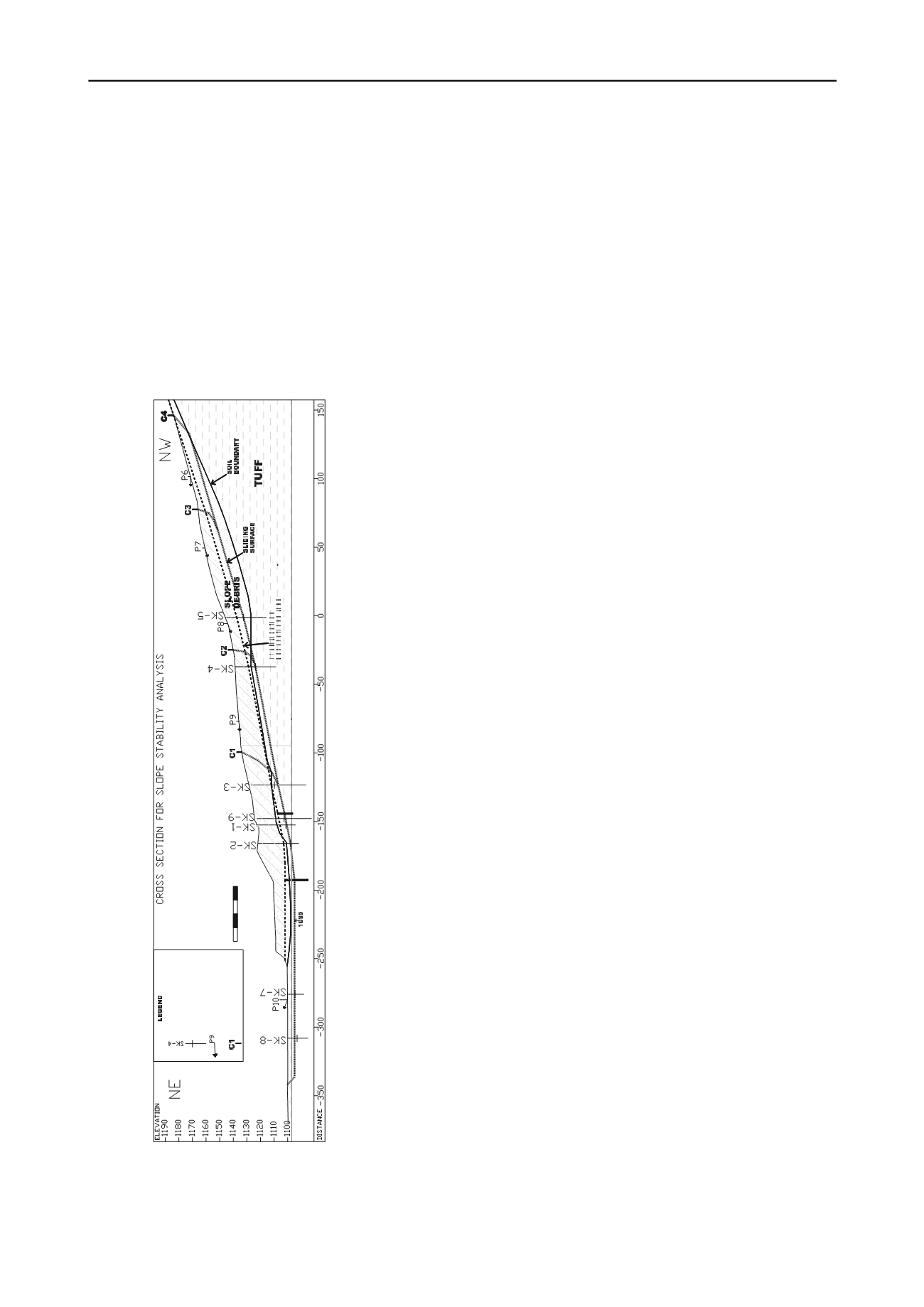
Figure 2. Cross section for the analyses
2.2
Stabilization Works for Foundation Excavation and
Prevention of the Slope Movements
As a result of the preliminary works it is understood that the
diameter of the stabilizing passive piles should be 1.2 m and
more than single pile row would be needed. The depth of the
sliding mass was 20 m at the centerline. It was not possible to
stabilize this amount of soil mass by two rows of piles only. So
stabilizing excavations were needed to decrease the amount of
sliding mass (about half of the sliding depth was
gure 2), and then the following piled analyses were
performed.
1.Slope Stability (GEOSLOPE 6.02, SLIDE 5.014) /
Structural Analyses (SAP 2000, V8.4)
2. Finite Element Method (PLAXIS 2D, V8.6)
In this stabilization program, one row of stabilizing piles are
placed at an upper level (Pile Row K1 in Figure 1). The lower
row of piles (Pile Row K2 in Figure 1) will also have a function
of retaining wall for the facility. To decrease the moment and
the displacements of the piles in this second row, permanent
ground anchorages were planned at the top beam of the piles.
The most critical issue in the analyses were the excavation
works for the foundation of the facility which would be
performed after the stabilizing works were
of the excavations just behind the second row
pile displacements and the moments were inc
row of piles. This critical concept was best configured in 2D
finite element analyses (figure 3).
2.3
Finite Element and Limit State Analyses
The place of the two rows of the stabilizing piles is shown in the
plan view in Figure 1. In the analyses the construction stages
were excavations for stabilization, the construction of the piles
and the foundation excavations to the 1095 m elevation just in
front of the K2 Pile Row. For the drained analyses of the K1
pile row it was found that the pile head displacement as 18 cm,
the shear force as 468 kN/m and the bending moment as 1240
kN.m/m. The same values for the K2 pile row were 10.8 cm,
387 kN/m and 970 kN.m/m, respectively.
The horizontal peak ground acceleration at the construction
site was accepted as 0.25g and accordingly the seismic stability
of the stabilizing system was also checked. The slope stability
analyses of the final stage of the works were repeated for a
horizontal seismic ground acceleration of 0.125g.
The cohesive soil exerts a pressure on the piles when it tries
to pass between the piles forming a failure mechanism. This
pre sus
e to be checked (see Eq. 1). This equation is valid
re s is the pile center-to-center spacing and d is the
e diameter. If s<3d there will be a reduction up to a factor of
0.5.
. .
u
p c kD
(1)
Active and passive lateral earth pressures are represented by
spring constants k above and below sliding surface. The k
values for this case were 1.30 for the passive side of the lower
1.34 and 0.86 for the passive and active
l (K1) piles. These are lower than the limit
level (K2) piles and
side of the upper leve
values (Ergun, 2000).
3
CONCLUSION
A long landslide which progresses backwards had occurred
because of the foundation excavations of an industrial plant
which coincided with the toe of a historic landslide. The
construction works were stopped, and the landslide was
investigated through boreholes. The clayey debris (colluvium)
containing limestone cobbles and boulders had slided over
Thedirectionof the movement
(topographical survey point)
RUPTURE SURFACE
BOREHOLE
(the sliding surface from
inclinometer readings)
0 10 20 30 40


