2251
Technical Committee 208 /
Comité technique 208
Superficial
< 0.5
Shallow
0 -2
0.5 - 3
Medium
2 - 10
3 - 8
Deep
> 10
8 - 15
Very deep
> 30
> 15
Depending on the findings from the above mentioned work
packages (Ch. 2.1. to 2.4) four possible slope scenarios and
respective measures may be differentiated (Figure 1):
- A) stable without additional measures, no further action is
required.
- B) unstable due to changed boundary conditions and cannot
be stabilized with feasible measures. However, the slope
instability may be avoided by flattening the slope by
massive earth works.
- C) unstable due to changed boundary conditions but the
consequences of the instability do not affect the
serviceability of the reservoir and are therefore acceptable
and do not affect the serviceability of the facility.
- D) potentially unstable due to changed boundary conditions
but can be stabilized with additional stabilization measures:
for this case a toolbox is presented in Table 2; depending on
the geometry, of the potential slide and its failure mode, the
required measures may be chosen.
3 MITIGATION MEASURES
3.1
Superficial and shallow landslide mitigation measures
Shallow landslide (i.e. < 3m thick, see table 1) mitigation
measures aim to prevent surface erosion and to improve the
drainage capacity of the uppermost meters. Appropriate
measures comprise, e.g.:
- drainage trenches, to reduce the length of drainage path and
hence erosion; they may be lined with geotextiles and
combined with drainage tubes;
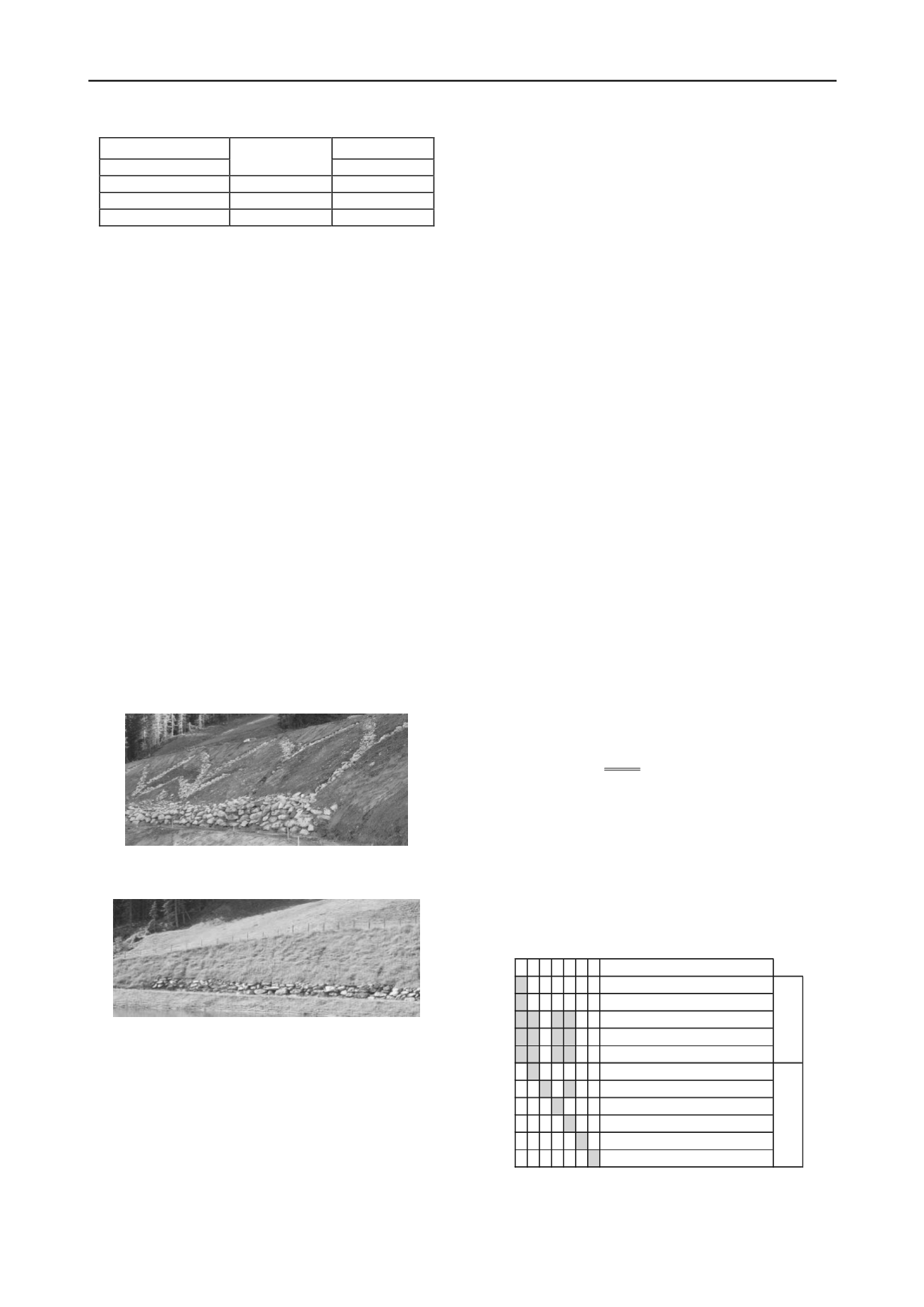
Figure 3: reservoir slope featuring drainage trenches above the storage
level.
- wave protection, to prevent soil from external erosion
Figure 4: Wave protection measure (stone wall) in an impounded
reservoir.
- cultivated crib walls;
- geomembranes, along with soil nailing, gabion mattresses
and/or blocks as surface erosion protection, especially for
fine-grained soils; nails are used primarily to stabilize the
geotextile and secondarily to stabilize the soil itself;
- geomembranes, along with flat gabions, as erosion
protection measure.
Protection in the vicinity of road cuts above the shoreline
comprises gabion walls and soil nailing, used as artificially
steepened natural slope measure.
3.2
Medium to deep seated landslide mitigation measures
By installing a defined grid of geotextile wrapped stone
columns, the shear strength of the soil may increase and the
length of the drainage path in the soil can be shortened. Both
effects increase the slope stability. Also, by means of local soil
substitution with material of higher shear strength and
permeability, the stability and erosion protection are improved.
Supporting embankments may be used to prevent erosion
and to stabilize deep seated potential slip circles. Such
embankments have already been successfully applied to
stabilize unstable slopes of operating hydropower facilities.
If subaquatic soil instabilities (i.e. below the reservoir water
level) are accepted, which may acceptable if they do not
influence the serviceability of the reservoir, but the shore above
water level has to be protected, a pile wall at the height of the
maximum water level may be installed as a protection measure.
3.3
Very deep seated landslide mitigation measures
Very deep seated (i.e. > 15 m thick, see table 1) landslides
generally require cost-extensive mitigation and monitoring
measures such as drainage drillings and adits (Bonzanigo et al.
2007, Zangerl et al. 2010).
4 COMBINATIONS OF MEASURES
In order to find feasible and appropriate combinations of
mitigation measures, Table 2 presents a matrix of scenarios
(scenarios 1 to 7).
- Scenario 1 represents possible combinations of protection
measures below storage level to prevent superficial mass
movements and erosion.
- Scenarios 2 to 7 combine mitigation measures against
potential superficial instability with medium to deep seated
mass movements. Whereas in scenario 2 flattening of the
upper part of the slope reduces the driving force of a
potential instability, in scenario 3, the increase of the safety
level is obtained by increasing the resisting force at the toe
of the slope. Note that for scenario 3 the safety against
surface erosion is given when using accordingly graded fill
material. In contrast, when combining measures as shown in
scenario 4, measures for both failure mechanisms have to be
designed individually. This may also be the case for
scenario 5.
- The most drastic measure is hence the soil replacement
depicted as scenario 6, whereas in scenario 7 the goal is that
the safety of the slope above the impoundment level
remains, without taking into consideration the stability
below the measure.
Table 2: Matrix of combinations. +: appropriate measure/combination. `
nappropriate measure/combination.
i
Scenario
drainage trench
wave protection
geomembranes with gabbion mattresses
geomembranes with soil nailing
cultivated protection walls
flatten slope geometry by soil removal
flatten slope geometry by support fill
Deep soil nailing
soil improvement (e.g. vibro replacement)
soil replacement
pile wall
7
-
-
-
-
-
-
-
-
-
-
+
6
-
-
-
-
-
-
-
-
-
+ -
5
-
-
+ + + -
+ -
+ -
-
4
-
-
+ + + -
-
+ -
-
-
3
-
-
-
-
-
-
+ -
-
-
-
2
-
-
+ + + + -
-
-
-
-
1
+ + + + + -
-
-
-
-
-
superficial
instability
shallowto mediumdeep
seatedinstability


