2254
Proceedings of the 18
th
International Conference on Soil Mechanics and Geotechnical Engineering, Paris 2013
Proceedings of the 18
th
International Conference on Soil Mechanics and Geotechnical Engineering, Paris 2013
. In this case the number of the
un
this way the parameters for the
slo
ut these parameters were not suitable to use for the whole tuff
n the analyses.
Material properti
sed in
lyses
D ed
drained
below that tuffs sometimes in clayey state and sometimes in
harder state are encountered.
2
ANALYSES AND RESULTS
In this section the types of the analyses , the results of the back-
analyses of the landslide movement and then the stabilization
works will be presented.
2.1
Back-Analyses and the Shear Strength Parameters
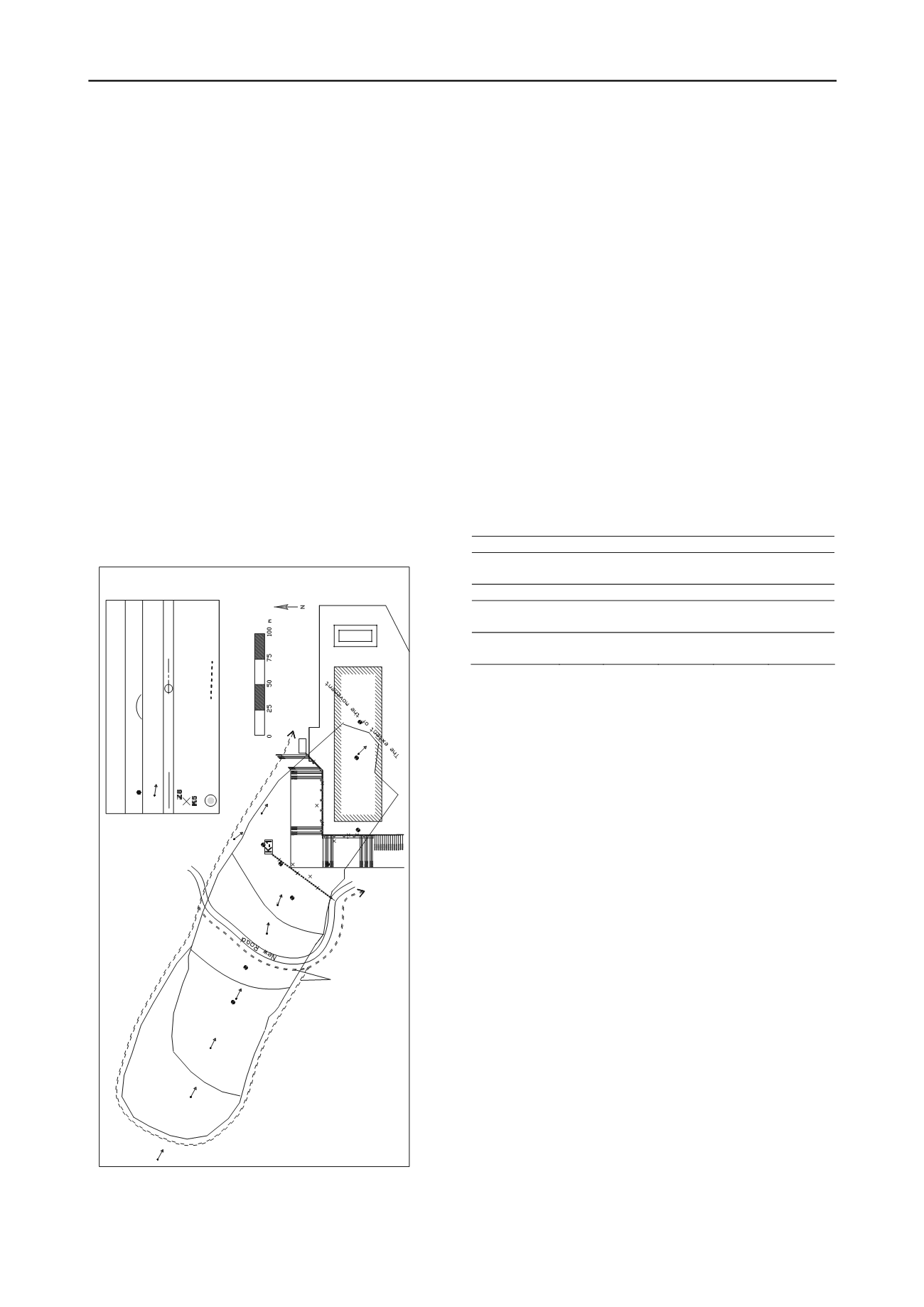
In all boreholes inclinometer readings were taken, and the depth
of the slip has been determined. As it is a fast movement, all
inclinometer pipes were sheared by the landslide (except SK-3
and SK-8) shortly after they are placed. These depths were
considered as the depth of the slip surface. The cross section of
the landslide were prepared according to the borehole data and
inclinometer readings and the scarps of the progressive slips.
The positions of the slope debris and tuff layers and also the
scarps of the progressive failure slides are shown in Figure 2.
The shear surface passes mostly through the colluvium material
in the upper half of the sliding mass, whereas it passes near the
contact between the colluvium and tuff (more within the tuff) in
the lower half of the sliding mass. There was no groundwater
level, however in stability analysis to be on the safe side some
water level is considered.
Figure 1. General layout plan
It was not easy to take samples from the sliding mass near the
shear surface, therefore only a limited number of soil samples
were tested in the laboratory. Determination of the soil
parameters at the sliding surface of a landslide at the limit
equilibrium state by the back analyses of the movement is a
widely used method. In this method the c and
parameter
couples are determined which give a factor of safety value of
one at the sliding surface. In the back analyses the cohesion and
angle of friction parameter couples for the tuff and the slope
debris layers are identified
knowns is four. They are decreased progressively using a
methodology given below.
At the first stage, the back analyses of sliding surfaces of C3
and C4 were performed. By
pe debris were determined as c
′
=5.6 kPa and
′
=15.7°, E
′
=35
MPa are used in the analyses.
At the second stage, calculations for sliding surfaces of C1
and C2 were performed. The above parameters were used for
slope debris, and the shear strength parameters for the tuff
layers were determined. The parameters for the weathered tuff
layer at the sliding level are assessed as c
′
=0 kPa and
′
= 9.2°.
B
layers. Table 1 summarizes the parameters used i
Table 1.
es u
ana
rain
Un
Material
c
′
(k )
(MPa)
(
)
Pa
′
(°)
E
′
c
u
(kPa)
E
u
MPa
Slope debris
5.6
15.7
35
60-75
20
Weathered tuff
(first 3 m)
0
9.2
100
60
Unweathered
tuff
20
25
60
250
130
Undrained triaxial compression and consolidated drained
direct shear tests were performed on the debris and tuff soil
samples from the boreholes which are located between the slope
debris and tuff layers. The results of these tests show that the
internal friction angle for the slope debris and fo
r the clay soil
originated form tuff are 15 to 20 and 10.2 respectively. This
back analyses.
-based and some of them
are
eflection, or the movement of the soil, they
are
findings support the results of the
2.2
. Slope Stabilization by Piles
Piles used in slope stabilization are subject to lateral force
caused by the movement of surrounding soil, and they are called
“passive piles” (Viggiani 1981; Poulos 1995). One of the major
issues in the design of these piles is the magnitude of the force
on the pile. Since this is related to the soil movement and soil
movement is influenced by the presence of piles, the interaction
between the passive piles and the soil is quite complicated.
There exists a number of empirical, analytical, and numerical
methods available in the literature about the design of piles used
in slope stabilization (Brinch Hansen 1961, De Beer 1977,
Fukuoka 1977, Ito and Matsui 1977, Sommer 1977, Winter et
al. 1983, Popescu 1991, Reese et al. 1992). Some of these
methods are pressure or displacement
numerical methods, such as finite element and finite
difference (Kourkoulis et al., 2012).
In the pressure or displacement based methods, the pile is
modeled as a beam supported by springs at its sides. A single
laterally loaded pile is considered, and the ultimate soil-pile
resistance is correlated with the undrained shear strength for
clays, and with the overburden stress and friction angle for
sands. In these methods group effects are taken into account by
using reduction factors. Although spring constants are
dependent on pile d
Facility Building
SK-1
SK-2
SK-3
SK-4
SK-5
SK-6
SK-9
SK-7 SK-8
P9
5.4 m
P8
4.8 m
P7
5.3 m
P6
3.3 m
P10
3.7 m
SK-8
C1
C2
C3
C4
C1
P9
2.5m
BOREHOLE
SLIDINGFACE
TOPOGRAPHIC SURVEY POINT
(the arrow shows the direction and magnitude of the novement)
LEGEND
K-2
P2
P3
P1
P5
12.4 m
16.4 m
10.0 m
0.17 m
K1
Z2
K3
Z4
K5
K6
K7
Z8
K9
Z10
K11
K12
Drainage
Channels
RUPTURE SURFACE
PILE ROW
INCLINOMETER
20 m LENGTH FOR SOIL INC. (Z..)
SAME LENGTH OF THE PILE FOR PILE INC. (K..)
DRAINAGE SHAFTS
DRAINAGE LINE
typically assumed constant. In the current study this
approach is used.


