2250
Proceedings of the 18
th
International Conference on Soil Mechanics and Geotechnical Engineering, Paris 2013
2.1
Site selection
The site selection process for hydropower reservoirs is driven
by the need to optimise decision criteria which are initially
mainly of an economic nature,.
In the best case, several sites are shortlisted based on
economic factors followed by comparisons of options and more
detailed feasibility studies including detailed geological and
geotechnical investigations and designs.
2.2
Geological and hydrogeological model
A geological and hydrogeological model may be developed
using the following investigation techniques (selection):
- geological site mapping, incl. structural geological surveys;
- remote sensing and terrain analyses (e.g. optical images,
LiDAR, DEMs );
- hydrogeological field surveys (mapping of springs, surface
flow systems incl. discharge measurements, recharge and
infiltration characteristics);
- groundwater measurements, tests and monitoring (spring
parameters e.g. EC, T and discharge, stage-discharge stream
gauges,
groundwater
elevation
gauges,
piezometers/hydraulic heads, tracer tests, hydrochemical
and isotopic analyses, etc.);
- core drillings with in-situ measurements and tests (e.g. core
SPTs, geophysical borehole logs, geotechnical and
hydraulic tests, e.g. packer tests, water pressure tests,
dilatometer tests) and (un)disturbed rock/soil sampling;
- geophysical surveys (surface and borehole seismics);
- slope monitoring (geodetic surveys, inclinometer
measurements and others).
Based on these data, a comprehensive rock mass model may be
established, which in turn constitutes the basis for the
subsequent steps (see Figure 1).
2.3
Geotechnical model and assessment of actual slope
stability
Based on the geological model (incl. results from lab and field
tests), characteristic soil parameters and a geotechnical model
are defined. “Characteristic” soil properties may be i) obtained
from field and lab tests and/or ii) back calculated from the
geological model, (taking into account the soil strata and slope
inclinations). In the latter case an assumption on earthquake
loads which have already been acting on the slope has to be
made and included in the back analyses. When using back
calculations it is assumed that the slope is in limit equilibrium.
Ideally both approaches should be combined.
These calculations yield values for the assessment of the
actual slope stability. However, these assessments are
commonly based on geological and geotechnical models of
limited accuracy due to a limited number of available results
from laboratory and field tests. Therefore, the “real” soil
parameters are to be verified at the latest at the stage of the first
impoundment of a reservoir.
2.4
Assessment of slope stability under changed boundary
conditions
The boundary conditions of reservoir slopes may change
drastically due to impoundment and rapid drawdown
Therefore the back calculated geotechnical slope model (see
above) has to be adapted to these changed boundary conditions
and the slope stability has to be reassessed. From this analysis
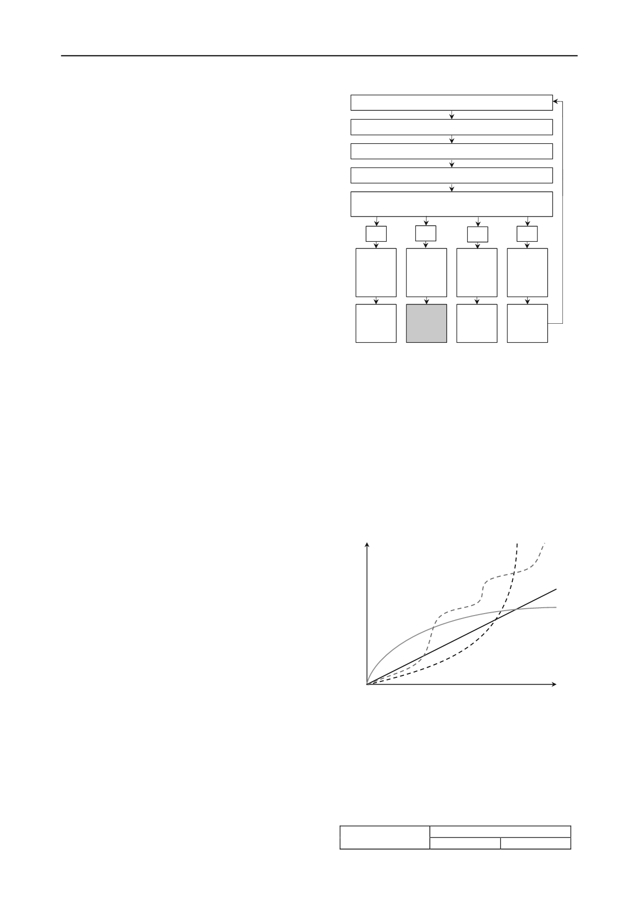
four different scenarios may be obtained (see Figure 1):
In the best case, the slope stability is not affected by the new
boundary conditions at all. This is the case when the failure
plane is located entirely above the shoreline.
The remaining three cases may be assessed according to i)
the size and shape of the potential landslide mass and ii) the
acceptance of the consequences of a failure.
geological model
geotechnical model
assessment of actual slope stability
assessment of slope stability under changed boundary
conditions
stable
without
additional
measures
unstable
but can be
stabilized
unstable
but
accepted
unstable
and cannot
be
stabilized
No further
action
required
Toolbox Monitoring
required
Avoid
and/or
remove
site selection
A
B
C
D
Figure 1: Flow chart for the assessment of slope stability (explanations ,
see text).
The decision whether a potential slope failure is acceptable
depends on various criteria: If the slope stability deteriorates,
proof has to be provided that the safety of the dam and its
surroundings are not affected. This means that the size and the
velocity of potential landslides do not cause critical tsunamis
overtopping the dam.
For this proof and the risk assessment, the slope deformation
behaviour has to be evaluated according to the types shown in
Figure 2. While deformation types 1 and 2 are commonly
unproblematic and type 3 requires a sound risk assessment, the
stick-slip behaviour of type 4 landslides is much more difficult
to predict. Such deformation behaviour requires intensive
monitoring and a fundamental knowledge of the soil properties
(Barla et al. 2010, Leobacher and Liegler 1998, Zangerl et al.
1999).
time
deformation
1
2
3
4
Figure 2: slope kinematics (temporal deformation types): (1) decreasing
slope velocity; (2) constant velocity; (3) accelerating and failing slope;
(4) episodic accelerated slope (after Keusen 1998)
Planning any mitigation measures depends on the geometry
and depth of landslides. Concerning this, the classification of
landslide thickness (according to BAFU 2009 and ICG 2011) is
shown in Table 1.
Table 1: Landslide categories as a function of the depth of movement
acc. to BAFU, 2009 and ICG 2011).
(
Depth of movement [m]
Category
BAFU 2009
ICG 2011


