1902
Proceedings of the 18t
h
International Conference on Soil Mechanics and Geotechnical Engineering, Paris 2013
.
4
3.5m
1.7m
7.8m
S3
S2
S1
2.0m
3.5m
0.5× 4=2.0m
CPT
Cuttings of slope
﴾
Failure occurred
after S7
﴿
S4
2.0m
30°
60°
S6
S7
S5
70°
75°
1.0m
Tarpaulin
4m
Concrete
wall
Cutting marks
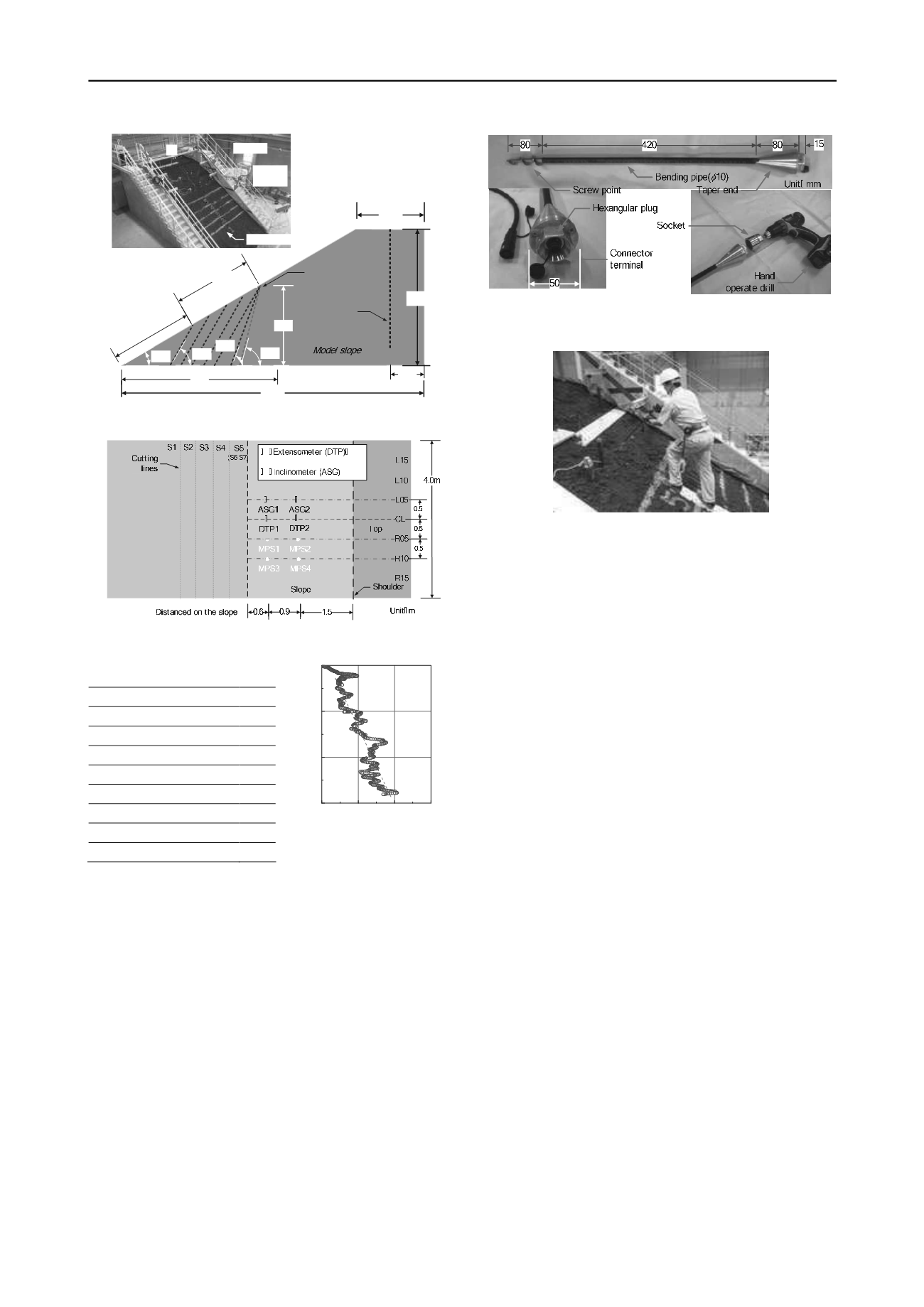
Figure 1. A profile view of model slope.
Figure 3. A plane view to show the installed position of sensors
0
500
1000
1500
- 3
- 2
- 1
0
Depth
d
(m)
Cone penetration resistance
q
c
(kN/ m
2
)
Figure 2. Relationship between
cone penetration resistance and
depth from the top of slope.
Seven steps of cuttings were carried out by construction
machinery in the toe of slope. 60 degrees angle in the cuttings
was performed from S1 to S5 that was 0.5m long from front to
back as shown in Figure 1. As for S6 and S7, the cutting angle
was increased to 70 degrees and 75 degrees, respectively. Thirty
minutes interval time between the steps was provided to observe
the movement of the slopes.
3.2
Installation of sensors
Three kinds of sensors, extensometers (DTP), inclinometers
(ASG), and compact shear strain meters (MPS), were installed
to measure the movement of the slope during the test. Figure 3
shows the installed positions of the sensors. Two sets of DTP
were installed to measure increment of the displacement
d
by
giving 0.9m interval at the center column (CL). Sensor units of
DTP were set on a beam bridging over the retaining walls while
extended wires were connected to pegs on the slope.
Figure 5. Shape and structure of a developed compact shear strain meter
(MPS).
Photo 1. Installation of MPS
Two sets of ASG were installed to measure an increment of
the angle of inclination
a
on the surface at the column of L05 at
same height as DTP. Four sets of MPS to be explained in the
following section were also installed to measure increment of
the interpreted shear strain
at the columns of both R05 and
R10 in the same manner as the installation in ASG.
4 MESUREMENT OF SHEAR STRAIN IN THE
SHALLOW SECTION
4.1
Development of compact shear strain meter
A compact shear strain meter called MPS was developed to
measure the shear strain in the shallow section of slopes
(Tamate. 2010). MPS made of compact size rod 0.6m in length,
10mm in diameter, and 3.6N in weight is shown in Figure 4. A
screw point of 80mm in length attached in the lower end
enables to penetrate the unit into the ground without pre-boring.
A taper end of 100mm in length is used to provide a lateral
compression to the surrounding soil so that MPS reacts to the
slope movement by its bending deformation. A connector
terminal for data transmission composed of 7 poles is mounted
at the center of a hexangular plug for rotational installation by a
hand drill.
A bending pipe of 420mm in length is positioned between the
screw point and the taper end. Four strain gages are pasted on
both front and back of the pipe so that the electrical output
increases with the bending deformation. A heat shrinkable tube
covers the pipe to protect the gages from surrounding soil at
installations. Since duration for the installation was less than 10
seconds, easy and quick installation is available in practice as
shown in Photo 1.
4.2
Basic idea for the monitoring
Figure 5 shows a schematic image of distribution of
displacement and shear strain in the slope. An increment of the
displacements occurs near the slip plane whereas the increment
converges as the distance increases.. Accordingly, major shear
strain develops along the slip plane. However, this study aims to
monitor the shear strain in the shallow section of slopes from
the easily application viewpoint (Tamate et al. 2009). MPS was
developed to measure the small shear strain in the shallow
sections easily.
Table 1.Soil properties of Kanto
loam.
Densityofsoilparticles
s
(g/cm
3
) 2.759
Sand (0.075
~
2mm) % 6.2
Silt (0.005
~
0.075mm) % 45.3
Clay (Diameter<0.005mm) % 48.5
Liquid limit
w
L
(%)
158.3
Plastic limit
w
p
(%)
97.7
Plasticity index
I
p
60.6
Dry density
dmax
(g/cm
3
)
0.665
Optimumwatercontent
w
opt
(%) 102.0


