1895
Technical Committee 206 /
Comité technique 206
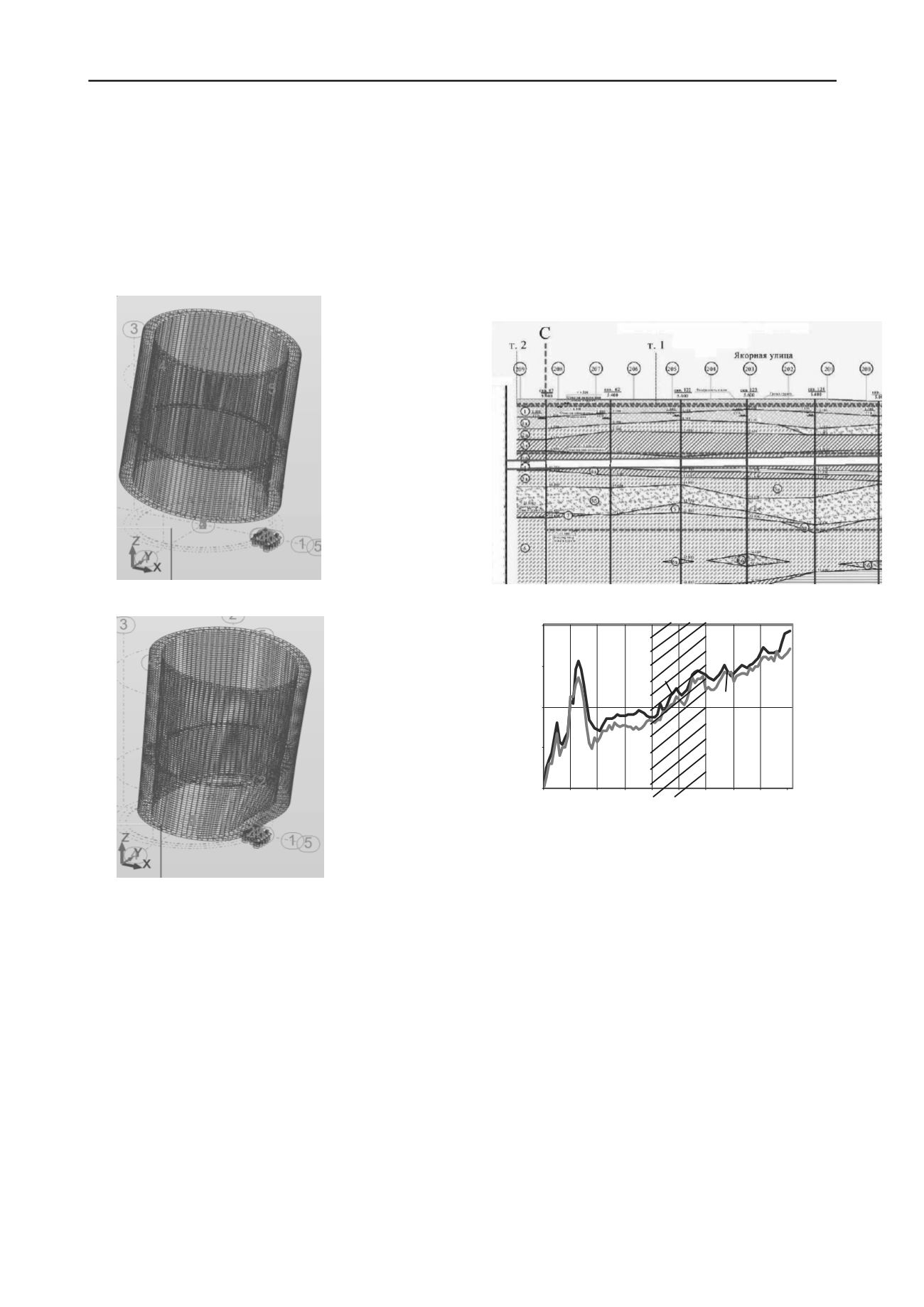
diameter of 66m and a height of 71m (with the number of
three-dimensional finite elements equal 50828), falling under
its own weight at an angle of 15 ° from a height of 140 cm on
the compliant soil (average coefficient of elasticity for
multilayer soil is taken K = 16500kN/m3). In the model
because of the inclination angle the friction forces on the
lateral side of the well were applied in the upper part of the
shell on one side and in the bottom part on the opposite side.
a)
b)
Figure 2. The results of numerical modeling of a sunk well with
diameter of 66 m and a height of 71 m for the conditions of a abrupt
landing (breakdown): a) the original position, and b) position after a
fall from a height of 1.4 m at an angle of 15 °.
The results of numerical modeling have shown (see Fig.
2) that in case of a dynamic blow (if the well is dropped from
a height of 140 cm) equivalent von Mises stresses in the
construct equal Sdin = 256MPa at the top of the shell and
Sdin = 1538MPa in the area of the bottom rest, which
respectively exceeds the limiting strength of concrete class
B30 [Spred] to 14 or more times, and the changes in the
geometry of the shell are observed.
Thus, already in the process of the well immersion the
construction of the well is damaged and the concrete is
disintegrated due to breakdowns. Later during operation
micro cracks lead to leakage, seepage and corrosion of
concrete. To further ensure the safety of operation of facilities
of this type it is necessary to strengthen and waterproof the
construct by high-pressure injection of polymer resins.
2.2 Geotechnical analysis of technical condition of the
sewage tunnels under intensive anthropogenic impact
and long term operation
Geotechnical analysis of the sewage tunnel was carried out
for the most typical section located in a zone of intense
dynamic impact of transport and the impact of new
construction.
Figure 3 shows the diagram of the tunnel compressions
for more than 35 years of service life.
a)
Absolutemarks,m
6,3
-2.0
-7.3
-9,3
-11,5
-14,2
-22,2
-24,0
-26,0
-32,0
b)
7.78
8.28
8.78
9.28
9.78
0
100
200
300
400
500
600
700
800
900
Figure 3. The diagram of comparison of the compressions on the arch
axis of the collector: a) engineering and geological section, typical for
laying-out sewage tunnels in St. Petersburg, b) the diagram of
compressions: 1 - survey results of 2010, 2 - executive survey data of
1975, 3-area of the collector, protected from the influence of the
construction be a screen of low modular material.
Uneven tunnel compressions, modified on the arch axis
range from 5 to 276 mm. Comparative analysis of engineering
and geological section on the tunnel route and its placement
on the plan relative to the traffic junction showed that the
greatest compressions up to 276 mm are located in the area of
the tunnel under intense dynamic effects of the traffic, passing
the layer of thixotropic quaternary deposits.
Evaluation of the dynamic impact of the transport was
carried out by the study of the oscillatory process with a set of
manifold gauges CM TSP installed in the arch and blocks of
the recording equipment (Perminov N.A, 2011)
The frequency of the oscillations of the collector during
various traffic loads from 15 to 35 Hz, and the vibration
amplitude to 35-70 microns was recorded. According to the
research (Goldshtein M.N., Lapidus L.S., Reznikov O.M.,
Storozhenko V.I., Sinaevsky N.I, 1973) for this type of
ground deposits and the appropriate level of the dynamic
effects the decrease of strength characteristics C and φ is up to
35% and 17%, respectively. To ensure the operational
Расстояние,м
Осадки,м
1
3
Compressions, m
2
Distance, m


