1890
Proceedings of the 18t
h
International Conference on Soil Mechanics and Geotechnical Engineering, Paris 2013
Proceedings of the 18
th
International Conference on Soil Mechanics and Geotechnical Engineering, Paris 2013
3
1
3
1
Mx
i
p
p
My
j
p j
p i
ij
p
u z
yNxNc
(6)
where
n
h
is the number which satisfies equation (4).
Figure 1. 3-dimensional coordinate space for drawing deformation of
retaining wall
2.2
Use of measured inclination
In the monitoring of the retaining wall, we often measure not
the displacement but the inclination because of its easiness. For
this reason, it is important for developing the method to take
incline data for evaluating the deformation. As follows, we
show the proposed method for using the incline data.
The function
R
(
f
) is divided into two functions,
R
h
(
f
) and
R
d
(
f
).
R
h
(
f
) expresses the sufficiency degree of displacements,
and
R
d
(
f
) expresses that of inclines. Using these functions,
R
(
f
)
is expressed as follow equation:
f R f R fR
d
h
(7)
where
γ
describes the weight of the sufficiency of inclines.
R
h
(
f
)
is expressed by equation (5).
On the other hand,
R
d
(
f
) is defined as follows. At the position
where an inclinometer located, (
x
q
,
y
q
,
z
q
), the derivative of the
function
f
is described by the following equation.
q
q q y
yx f
tan
,
(8)
Therefore, the functional
R
d
(
f
) is expressed as following
equation:
d
n
q
Mx
i
My
j
j
i
ij
d
n
yNxNc
f R
d
2
3
1
3
1
tan
(9)
where
n
d
is the number of the obtained incline data.
3 SIMULATION OF LOADING TEST OF MODEL WALL
3.1
Loading test of model wall
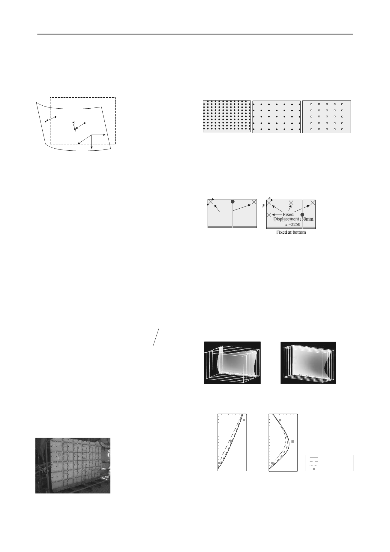
Figure 2 shows the photograph of loading test. The wall was 2m
in height, 3m in width and 10mm in thickness. The loading was
conducted for several cases, changing boundary conditions and
displacement. During the loading, the displacement and the
incline of the wall were measured using a lot of measurement
equipments. In the following simulation, we used only the data
obtained from the survey by total station (T.S.) and
inclinometers.
Figure 2. Loading test of model wall.
3.2
Conditions of simulation
Figure 3 shows the arrangement of measurement equipments
used in the simulations. (a) is the arrangement using all 128
points for the survey by T.S., (b) is using only 35 points, and (c)
is using 25 inclinometers. Figure 9 shows the pattern of loading.
※●
:Targets for T.S.
□
: Inclinometers
(a) 128 targets for
T.S.
(b) 35 targets for
T.S.
(c) 25 inclinometers
Figure 3. Arrangement of measuring points used in simulations
Figure 4 shows the arrangement of measurement equipments
used in this simulation. In CASE1, 80 mm displacement was
given at the top center of the wall. In CASE2, 30 mm
displacement was given at the right middle part.
(a) CASE1
(b) CASE2
Figure 4. Loading cases used in simulation
3.3
Results of simulation
Figure 5 shows the simulated and visualized surface using 128
points for T.S. (arrangement (a) as shown in figure 3) in both
loading cases. Figure 6 shows the distributions of displacement
at the cross section shown in figure 4, in both loading cases. In
figure 5, displacement obtained from the contact-type
displacement gauges was also plotted. From these figures, it is
seemed to be that the simulation could describe the deformed
surface in 3-dimension. Furthermore, the simulated
displacement for each case almost coincides with measured
results using the cross-section displacement gauges, regardless
of arrangements or kind of used measurement equipments.
(a) CASE1
(b) CASE2
Figure 5. Evaluated and visualized deformations of wall.
(a) CASE1
(b) CASE2
Figure 6. Distributions of displacement at cross section.
From these results, it was revealed that the developed
method was suitable for the evaluation and visualization of the
deformation of earth retaining wall.
u
p
(
x
p
,
y
p
)
(
x
q
,
y
q
)
f
(
x
,
y
)=
z
y
x
z
q
0
40
80
020 40
0
500
1000
1500
2000
0 20 40 60 80
Depth
(
mm
)
Displacement
(
mm
)
0
500
1000
1500
2000
0 10 20 30 40
Depth
(
mm
)
Displacement
(
mm
)
0501000 2
0 20 40 60 80
Displacement
(
mm
)
128 targets for T.S.
35 targets for T.S.
25 inclinometers
Displacement gauges
Displacement
:
80mm
Fixed at bottom
Fixed
x
=1500
x
y


