1880
Proceedings of the 18t
h
International Conference on Soil Mechanics and Geotechnical Engineering, Paris 2013
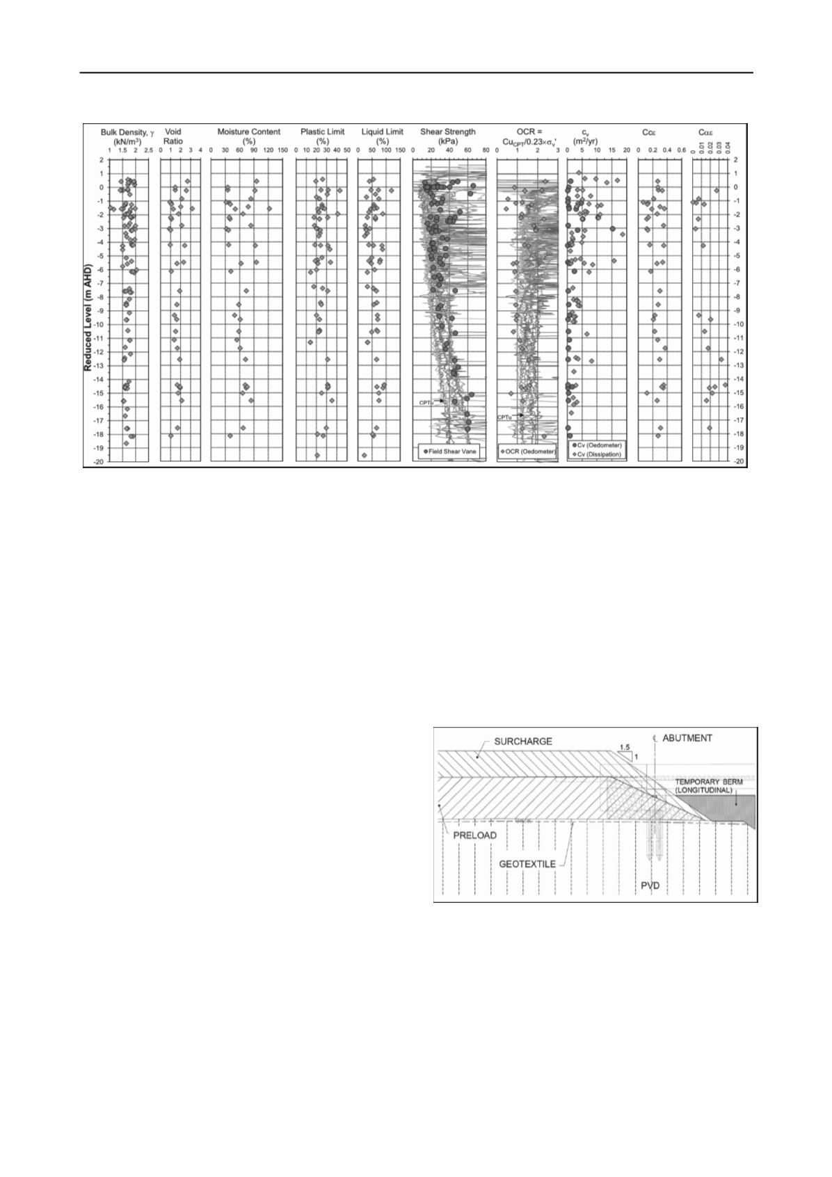
Figure 1: Soil test results - Airport Interchange precinct
Deposited during previous lower sea level, Pleistocene clay
(P-C) was found to be characterised by less compressible
stratum including stiff to hard clays and medium dense (or
denser) sand layer. The ground water level was observed to be
within 1-2m of the natural ground surface. The design ground
water table was assumed at the ground surface level prior to
construction (approximately RL 1.3m).
2.2
Geotechnical design parameters
The geotechnical parameters adopted for design and back-
analysis of BR25A bridge approach are summarised in Table 1.
Design parameters were derived taking into consideration the
potential variability in the ground conditions and were
calibrated against monitoring results during construction stage.
The coefficient of consolidation in the horizontal direction (c
h
)
was assumed to be 2c
v
and this ratio was found to be
appropriate based on the back-analysis of field measurements.
Site investigation data indicated variation in strength,
compressibility and hydraulic conductivity with depth and
location within the Airport Interchange area. Field results from
this vicinity indicate that the undrained shear strength (Cu) of
the compressible clay increases with depth from approximately
10kPa to 60kPa. Cu values derived from piezocone were
calibrated against the shear strength determined from the field
shear vane. For geotechnical design, a characteristic Cu value of
20 + 0.6z1 (kPa) for UH-C and 23.6 + 2.7z2 (kPa) for LH-C
was selected, where z1= 0 at RL 0 and z2= 0 at RL -6. Over-
consolidation ratios (OCR) were derived from Oedometer and
piezocone data. Figure 1 shows field and laboratory test results.
3 ALTERNATIVE DESIGN DETAILS
The alternative design philosophy involved initially improving
the shear strength and compressibility characteristics of the soft
soil by 6 months preloading in combination with placement of
4.3m surcharge. High strength geotextile (2 layers of
WX600/50) and prefabricated wick drains (1.0m triangular
pattern) were utilised for stability control. Refer to Figure 2 for
schematic design arrangement nominated during design stage 1.
To facilitate construction haulage, a 2m high temporary
berm in the longitudinal direction was proposed and this
stabilising effect was incorporated in the design. The use of
temporary berm achieved a reduction in the high strength
geotextile requirement for stability control.
Following conclusion of preload, installation of final
settlement transition treatment was anticipated, following
review of actual performance of the embankment during
preloading. The ground transition treatment for the alternative
approach comprised 3 transverse rows of unreinforced concrete
CFA columns (0.6m diameter on a 2.5m square grid with a UCS
of 40MPa) overlain by a 20m long geotextile reinforced
mattress to provide adequate pavement transition (see Figure 3).
Two layers of WX1100/100 were specified in the longitudinal
direction and one layer of WX200/50 in the lateral direction for
the geotextile mattress. As a Stage 3 optimisation, 1m of
embankment fill was excavated and replaced with lightweight
fill (flyash) to increase the final over-consolidation ratio of the
foundation soils and decrease preload period from 6 months to
2.4 months.
Figure 2: Typical stability and settlement control (schematic)
4 ALTERNATIVE DESIGN METHODOLOGY
The alternative design comprised a 3 staged approach to design,
which occurred across the design and construction stages for the
BR25A bridge approach.
4.1
Stage 1 methodology
Stage 1 involved undertaking design calculations to predict the
required ground treatment to meet the settlement and stability
criteria for the bridge approach transition. To meet the
prescribed settlement criteria of 50mm (max) at the abutment


