1877
Technical Committee 206 /
Comité technique 206
5 MEASURES DURING THE EXECUTION
It was considered to be important to specify the most vulnerable
processes into a number of documents that made it possible to
control the processes:
- the excavation plan describes the sequence of the execution
of the panels of the diaphragm wall as to minimize the
possibility that a leak will occur during the night;
- the supervision plan for the construction of the diaphragm
wall and for the excavation of the building pit is meant to detect
imperfections in an early stage during the excavation;
- the calamity plan describes the risks connected to the
construction of the diaphragm wall and the available mitigating
measures at the moment of signaling a (potential) leak or a
threatening calamity;
- results of monitoring activities and records give detailed
information on the execution of each panel, and of possible
imperfections. It is of utmost importance that the content of the
documents and the point in time of handing them in are
mutually agreed;
The results of the supervision by both the principal and the
contractor are discussed at the building meetings, and a separate
regular monitoring meeting with all persons concerned was
convened.
6 ASSESSMENT OF DIAPHRAGM WALL QUALITY
All relevant data have been evaluated to determine potential
weak-spots in the diaphragm wall along the excavation
circumference.
6.1 Pumping test
The pumping test to check the water tightness of the diaphragm
walls was executed in June 2010. The measuring results showed
that the water tightness of the building pit as a whole met the
requirements as formulated in the permit for water extraction.
This implicated that the average quality of the diaphragm walls
came up to expectations about water tightness in not excavated
circumstances.
6.2 Field observations
Field observations by both the contractor and the supervisors of
the City of Rotterdam were meant to record regular and any
extraordinary circumstances during the building process of each
individual panel. In practice, general data on the duration of the
consecutive building stages (a.o. excavating, refreshing of
bentonite suspension, lowering of steel reinforcement,
concreting) and identification of excavated soil type (sand or
clay) have been recorded. For some panels, underground
obstacles were encountered.
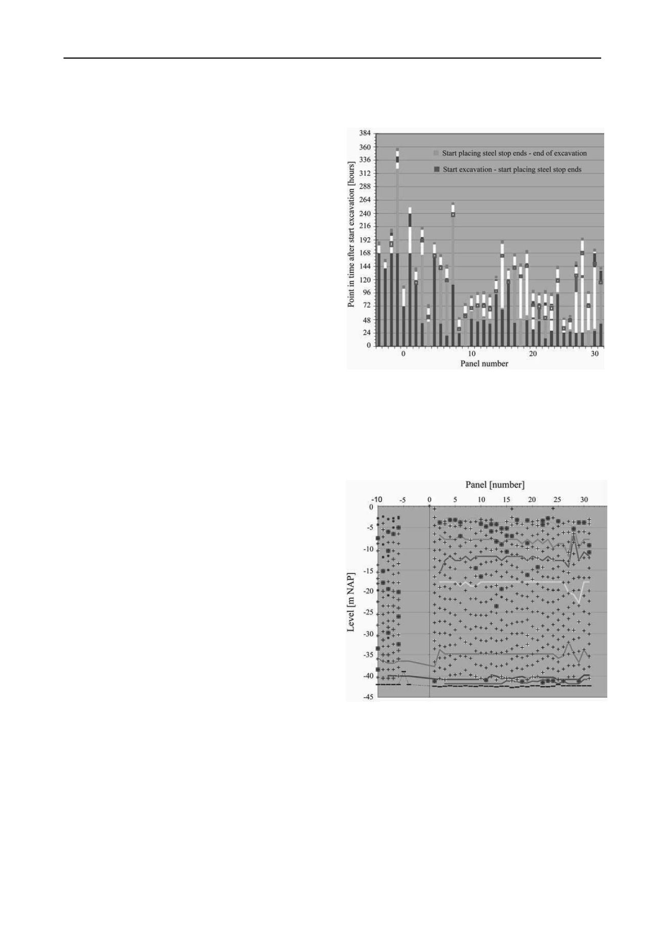
6.3 As-built documents
Information from as-built documents has been thoroughly
examined to detect any hazardous sections of the diaphragm
panel. These data have been visualized as for example shown in
Figures 3 to 5. Figure 3 shows amongst other things the elapsed
time between:
- the start of the excavation of the trench and the start of the
installation of the steel stop ends;
- the start of the installation of the steel stop ends and the end
of the excavation of the trench;
- the end of the excavation of the trench and the start of the
cleaning of the concrete surface;
- the start of the cleaning of the concrete surface and the start
of the installation of the reinforcement cage;
- the end of the installation of the reinforcement cage and the
commencement of concreting.
Long periods of elapsed time for a particular activity may
indicate an increased risk of imperfections.
Figure 3. Continuity of the production process.
Figure 4 shows the calculated deviation of wall thickness as
can be calculated from the concreting progress reports. From
Figure 4 it can be identified where the panels are suspected to
have a reduced thickness of more than 0.2 m. However, it is
recommended to have more detailed information on the
progress of the concreting process for future projects, as to
increase the resolution (reliability) of this graph.
Figure 4. Deviation of panel width (data originating from leveling data
and concrete consumption). The separation of the different soil layers as
derived of excavation data and of geotechnical investigations is also
indicated.
Figure 5 shows the position of all diaphragm wall panels at
40 m depth, as derived from crane operating monitoring
equipment. Most of the panels have been excavated in two or
three parts, thus giving at least two monitoring records
(inclination and deviation vs. excavation depth) per panel. From
Figure 5 it can be identified where the panels are suspected to
have insufficient overlap. The diaphragm wall thickness as
designed was 1.20 m; the allowable position with respect to
overlap (zone width of 1.60 m at 40 m depth) follows from the
2% deviation of the verticality.


