1868
Proceedings of the 18t
h
International Conference on Soil Mechanics and Geotechnical Engineering, Paris 2013
• Optical strands (fiber optics, OSMOS)
• Traditional inclinometer (GEO)
• Draw Tower Grating (fiber optics, Belgian Building
Research Institute (BBRI))
• BOTDR (fiber optics, Cambridge University)
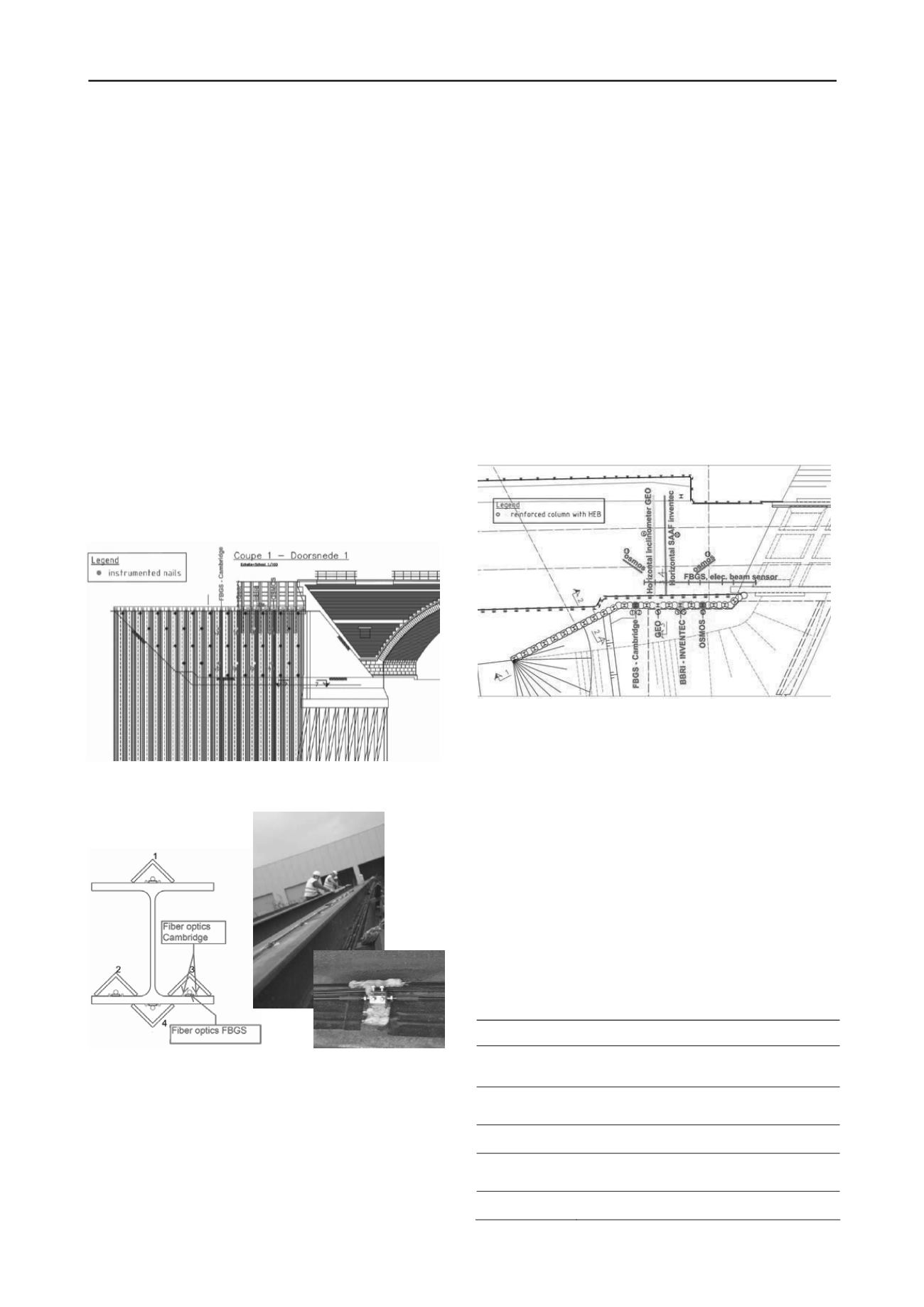
The equipment for measuring the deformation of the wall or
stresses in the wall, is placed on 4 HEB profiles which are
lowered over their full length in the jet grout wall. Figure 2
shows a front view of the excavation site and the location of the
instrumented profiles is indicated in red. Figure 3 shows a
drawing and some pictures of the FBG and BOTDR fibers
which are fixed to the HEB profile. The FBG fibers are fixed in
small anchor blocks which are welded to the HEB profile (size
of the anchor blocks is 18mm x 18mm). Those anchors are
placed every 0.5m in the upper 8m of the profile and every 2m
for the lower part. The BOTDR fibers measure the strain
continuously, but are locally glued to the HEB-profile (every
0.5m and 2m) for better comparison with the FBG data. To
measure deformations and moments perpendicular to the wall,
fibers are placed on the top and bottom flange. To measure
possible deformations parallel to the wall, two extra fibers are
placed at the sides of the bottom flange. Extra L-profiles, placed
above all fibers, are used as a protection during installation.
The other instrumentation was similarly fixed on the HEB
profiles by welding or gluing.
Figure 2. Front view of excavation with indication of instrumented HEB
profiles.
Figure 3. Sketch and pictures of a HEB profile which was instrumented
with two optical fiber systems.
1.2.2
Settlements behind the jet grout wall
As one of the main concerns during an excavation are the
settlements of the soil (and inherently the infrastructure) in the
vicinity of the excavation, the vertical deformation of the soil
behind the wall is one of the important parameters to be
monitored. In this project specifically, deformations of the
railroad track are to be avoided.
The deformations behind the wall are measured:
• with two horizontal inclinometers (a traditional one and a
continuous SAAF inclinometer) which are placed perpendicular
to the wall in the ballast underneath the rails. The inclinometers
are attached to a Berliner wall, which is located at one side of
the rails. It is assumed that this creates a fixed point;
• topographically: the rails are marked with survey nails
along a length of 100m and vertical deformations are measured
by topographic levelling at different stages of the project;
• with electrical beam sensors placed on the railway sleepers;
the beam sensor consists of an electrolytic tilt sensor attached to
a rigid metal beam. The beam, one to two meters long, is
mounted on anchor bolts that are set onto the sleepers. The
sensors are linked end to end, as to allow displacement values to
be accumulated from anchor to anchor to provide a profile of
differential movements or settlement.
• with two optical strands, placed at a certain angle with the
railway on the railroad tracks .
Figure 4 gives a top view of the instrumentation which is
placed on or underneath the railway tracks. It also shows the
different HEB profiles which were instrumented.
Figure 4. Top view of installed equipment.
A more detailed description of all installed equipment is
given in Van Alboom et al. 2012.
1.3
Design of the jet grout wall
Calculations of the jet grout wall are implemented in FLAC2D
by TUC Rail. They result in a maximum horizontal
displacement of 21 mm, a maximum moment of 65KNm and a
maximum settlement of 9mm behind the wall in the final
excavation phase. A more detailed description of the
calculations is given in Verstraelen et al. 2013.
1.4
Sequence of the execution phases
Table 1 gives the sequence of the execution phases, retrieved
from photos made on site every hour. As continuous monitoring
was performed, the influence of the executed works on the
movement of the soil could be assessed.
Table 1. Execution phases.
Date
information
22-23/10/2011
Installation of the instrumented HEB profiles
in the jet grout wall
3/11/2011
Excavation up to 1,25m below the top of the
concrete beam
06-09/11/2011
Installation of the first row of nails
06-07/12/2011
Excavation up to 3m below the top of the jet
grout wall
08-12/12/2011
Installation of the second row of nails


