1876
Proceedings of the 18t
h
International Conference on Soil Mechanics and Geotechnical Engineering, Paris 2013
2 SOIL CONDITIONS
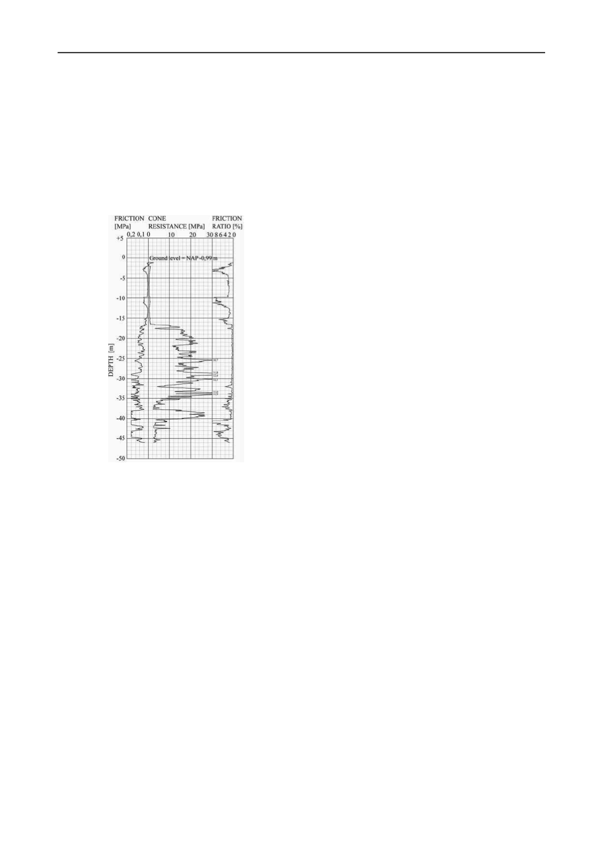
The ground level in the area is situated at about sea level. The
geotechnical profile of the Rotterdam city area consists of
anthropogenic layers (from ground level to about 5 m below sea
level), and soft Holocene peat and organic clay layers (from
about 5 to 17 m below sea level). Below this level Pleistocene
coarse sand layers are encountered up to 35 to 40 m below sea
level. These sand layers are underlain by the Formation of
Waalre, consisting of over consolidated clay and sand layers.
Figure 2 shows the result of a CPT. The phreatic groundwater
level is about 2 m below sea level.
Figure 2: Results of a CPT at car park Kruisplein.
3 RISK ANALYSIS
In this project the principal is responsible for the design, and the
contractor is responsible for the construction. The contractor is
obliged to present plans about the way the risks connected to the
building method are controlled, including relevant solutions and
mitigating measures.
The possibility of leakage into a building pit with diaphragm
walls is small, but the consequences may be very serious in case
groundwater flows into the building pit. Especially in an urban
environment a sand carrying leak is seen as a huge risk. Piles
are founded in the sand layer with the top at 17 m below sea
level. This is the same sand layer that may flow into the
building pit. There are several possible causes for leakage out of
this sand layer:
- the panels of the diaphragm wall are insufficiently
connected;
- the base of the panel is not or insufficiently connected to
the impermeable layer, for example as a result of the presence
of an obstacle;
- the concrete of the panel contains intrusions of sand, peat
or clay, that form weak spots in the diaphragm wall;
- the concrete of the panel contains bentonite, that forms
weak spots in the diaphragm wall.
The starting point in the design stage of the car park was that
the diaphragm walls would be placed at least 1.5 m into the
impermeable layers of the Formation of Waalre. At the deepest
point of the excavation the diaphragm wall must be able to
retain a groundwater pressure difference of about 20 m.
Measures to minimize the possibility of a leaking diaphragm
wall were prescribed in the contract. However, to minimize the
possibility of leakage, the most was expected of measures that
could facilitate the building process.
The outcome of the risk analysis indicated that to minimize
the possibility of a leaking diaphragm wall:
- additional requirements should be prescribed in the
contract;
- early observations of imperfections during the building
process are of utmost importance;
- the execution of the project has to be monitored adequately;
- the analysis of as-built records is essential as to identify
hazardous locations.
4 MEASURES IN THE CONTRACT
The building contract included Dutch standard RAW
specifications regarding quality control of the diaphragm wall
building process. The following additional contract
requirements have been defined:
- the verticality of the panels shall be within 0.5% of the
depth in both transverse and longitudinal directions;
- the horizontal deviations of the exposed face of a panel
shall be less than 100 mm;
- 150 mm wide water-stops (rubber profiles) shall be put into
every steel stop end of the diaphragm wall;
- the concrete surface of adjacent panels shall be cleaned
from bentonite cake before the commencement of concreting;
- the maximum rate of concrete rising in the trench shall be 6
m/h in the Holocene clay and peat layers;
- a good connection between the floors and the diaphragm
walls shall be secured. It is important not to drill unnecessary
additional holes for reinforcement bars into the diaphragm
walls. Zones of overlap of the reinforcement of the diaphragm
wall were not allowed at the locations of the reinforcing bars;
- the maximum aggregate particle size of the concrete shall
not exceed 16 mm.
Concreting records of the diaphragm wall panels had to be
made to register the following possible execution imperfections:
- the time during which the trench is left open before
concreting;
- the deviations of the steel stop ends;
- the deviations of the reinforcement;
- steel stop ends which are left behind;
- discontinuities in concreting.
After completing the diaphragm wall, and before starting the
excavation, a check had to be made on the permeability of the
building pit by means of generating a 20 m pressure difference
between inside and outside of the diaphragm wall. This
pumping test was meant to deliver information about the water
tightness of the diaphragm wall in the sand layer with the top at
17 m below sea level, and about the water tightness of the rather
impermeable layers at 40 m below sea level. A successful test
however, does not exclude leakage in the execution phase,
because the diaphragm wall will be excavated at one side, and
will deflect. This may result into open joints between the panels.
According to the contract four boreholes for so-called
sleeping wells had to be drilled around the building pit, to be
able to act quickly in case of a leak. The purpose of these
‘sleeping’ wells was, in case of a calamity, to decrease the
difference in water pressure between the inside and the outside
of the building pit as soon as possible. This will make it easier
to control the amount of groundwater that penetrates the
building pit. The installation of pumps and mains was not
required in the contract. The idea was that in case of a calamity
the mobilization period would be limited.


