1864
Proceedings of the 18t
h
International Conference on Soil Mechanics and Geotechnical Engineering, Paris 2013
level as shown in Figure 1. All existing piles were designed and
constructed by Cementation Skanska as under-ream piles.
The local geology comprises made ground overlying Terrace
Gravels, which in turn rests on London Clay. The top of the
London Clay is within 2m of the existing basement level and all
piles, both existing and new, are founded within this stratum.
The existing piles were designed to carry total building loads of
350,100kN and 33,900kN for those inside and outside the
basement, respectively. There are a series of heavily reinforced
pile caps and ground beams, and their thickness varies across
the site. Typically the ground beams are around 1000mm to
1500mm deep at pile positions, and the pile caps vary from
1500mm to 4150mm deep. This complex pile foundation
system practically constrains the available physical space for
designing new piles.
The scheme design was developed with the existing building
arrangement and existing foundation arrangement in mind.
However, with the proposed building being taller (sixteen floors
in lieu of eight) and the main stability systems located in
slightly different areas, the existing foundations proved to be
inadequate as a whole. The result of technical studies
demonstrated that the existing piles were overloaded by some
85,000 kN when compared to actual load carried originally.
To enhance the existing piles where they were found to have
inadequate capacity, supplementary piles needed to be installed.
Figure 2 shows the significant subsurface congestion beneath
the site when new piles were installed.
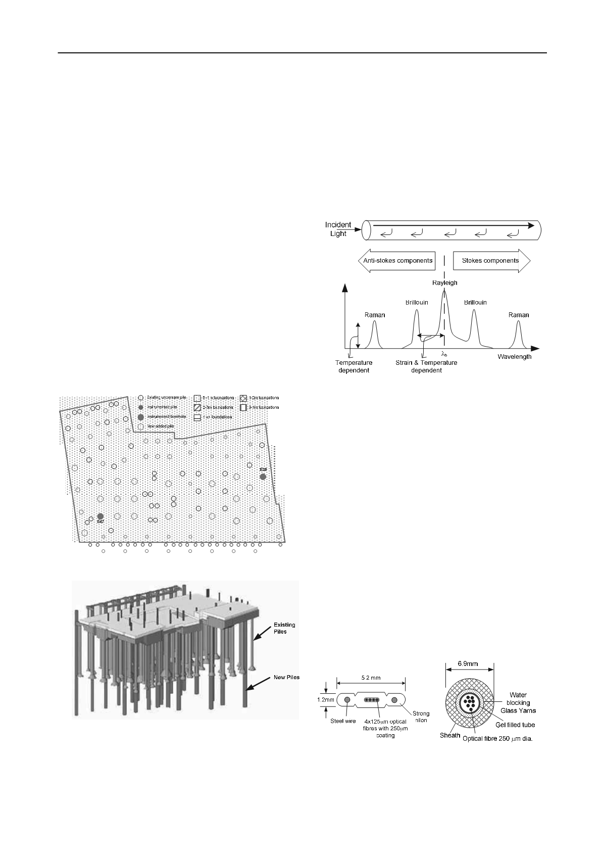
Figure 1. Pile layout and physical constraints to substructure.
Figure 2. Foundation system including the existing and new piles.
2.2 BOTDR sensing principle
Brillouin Optical Time Domain Reflectometer (BOTDR) was
adopted for this project. It provides sensitive strain
measurement from the reflected light that travels along the
standard single mode fibre optic cable. The entire fibre cable
can be considered as the sensor itself. When the light travels in
the optical fibre sensor, the majority of it travels through but a
small fraction is back scattered as shown in Figure 3. In the
back scattered spectrum, where only Brillouin spectrums are
temperature and strain dependent, the frequency shift of the
Brillouin spectrum indicates the local change in the fibre
properties induced by the change of strain and temperature.
Hence, the change in strain and temperature along the fibre
optic sensor is proportional to the frequency shift, which can be
detected by the BOTDR analyzer. The analyzer used in this
study is capable to sample 1 m averaged strain or temperature at
every 5 cm with an accuracy of 50
με
and up to a distance of
10km.
Scattered Light Power
Figure 3. The spectrum of backscattered light.
Due to the principle of Brillouin backscattered sensing, the
system registers strain induced by the elongation of the optical
fibre itself and the strain resulted from temperature change.
Therefore it is necessary to incorporate two different types of
optical fibre sensing cables to compensate for temperature
effect. Figure 4 shows two types of cables which have been
carefully calibrated and widely used for infrastructure sensing
(Klar et al., 2006; Mohammed, 2012). Figure 4a shows the
strain sensing cable, which consists of four optical fibre
members tightly bonded by strong nylon material. This is to
ensure the strain can be fully transferred from the nylon coating
to the optical fibre itself. Two steel wires at both ends reinforce
the cable and make it robust enough to survive in the harsh
construction environment. The temperature cable shown in
Figure 4b consists of several optical fibres in a gel filled tube,
so that it can contract and expand only under temperature
effects, independent of mechanical strain.
The use of optical fibre technology has numerous advantages
over conventional monitoring systems, it is capable of providing
a continuous and full length strain profile and this makes it
possible to monitor for cracking of the pile along its full depth.
The continuous strain profile also provides a picture of what is
happening over the full pile shaft; this would not be possible
with traditional single point based system such as vibrating
strain gauges or extensometers.
(a)
(b)
Figure 4. a) strain sensing, b) temperature sensing cable.
2.3 Instrumentations and field installation
Prior to demolishing the building, an under-ream pile (E47, see
Fig. 1) was selected on site to be cored to full depth for


