1894
Proceedings of the 18t
h
International Conference on Soil Mechanics and Geotechnical Engineering, Paris 2013
Analysis of the materials of the investigations shows that
at the moment 60% of gravity sewage tunnels and 80% of
pressure sewage tunnels require repairs and sanitation.
Instrumental probing (with geological radar) shows that 70-
75% of inner surface of pumping plants wells and sewage
tunnels have continuity violation and cracks which require
strengthening of construct and renewal of waterproof shell.
Table 2. The list of defects typical for the long-term operated
(more than 30-45 years) deep pumping plants and tunnel collectors.
Location
of
the
defect
Description and photo of the defect
Sunk
wells
walls
Up to -25÷30m
marks.
On
some
sections of sunk
well
walls
there’s leakage
through knots.
In the knots
area
there’s
leakage
of
concrete
corrosion.
Defects are of
repetitive
nature.
-30 to -40÷45m
marks.
On the surface
of the wall
there’re marks
of
intense
leakage through
the
cracks.
Defects are of
mass nature. In
the knots area
there’s leakage
of
concrete
corrosion.
More than -45m
marks.
On the surface
of the wall
there’re marks
of
intense
leakage through
the cracks. In
the knots area
there’s leakage
of
concrete
corrosion.
Defects are of
mass nature.
Sewage
tunnels
lining
Tubing lining
shows leakage.
Underground
waters go to the
collector
through cracks
and knots in
solid
ferroconcrete
inside
lining.
There’s leakage
of
concrete
corrosion and
salts.
There’s
a
water-filled
space in the
form of a thin
gap between the
tubing
lining
and the jacket
of
collector.
Defects
are
hidden, can be
found
geological radar
probing
of
collector
facilities.
Solid
ferroconcrete
inner
lining
(jacket)
is
destroyed,
there’s intense
leakage
in
welded seams.
2. ANALYSIS OF FACTORS INFLUENCING THE
SAFETY OF DEEP ENGINEERING STRUCTURES
AND MEASURES FOR THEIR ELIMINATION
2.1 Analysis of monitoring data for the construction of sunk
large pumping plants and of the inspection results after
long term operation
The slotted soil column for construction of sunk wells for
main pumping plants in the conditions of St. Petersburg is
characterized as follows: top part is presented by quaternary
beddings to the depth of 14.0-25.0 meters (middle-density
water-saturated dust sand E=11 MPa, C=0 MPa,
=30
;
laminar silt sandy loam Е=4 MPa, С=0.01 MPa,
=15
;
laminar silt loam, very soft Е=9 MPa, С=0.025 MPa,
=16;
semisolid silt loam with gravel, pebbles Е=14 MPa, С=0.028
MPa,
=28
), lower part is represented by top of positioned
Proterozoic bluestone (Е=19 MPa, С=0.04
0.06 MPa,
=18-
21
).
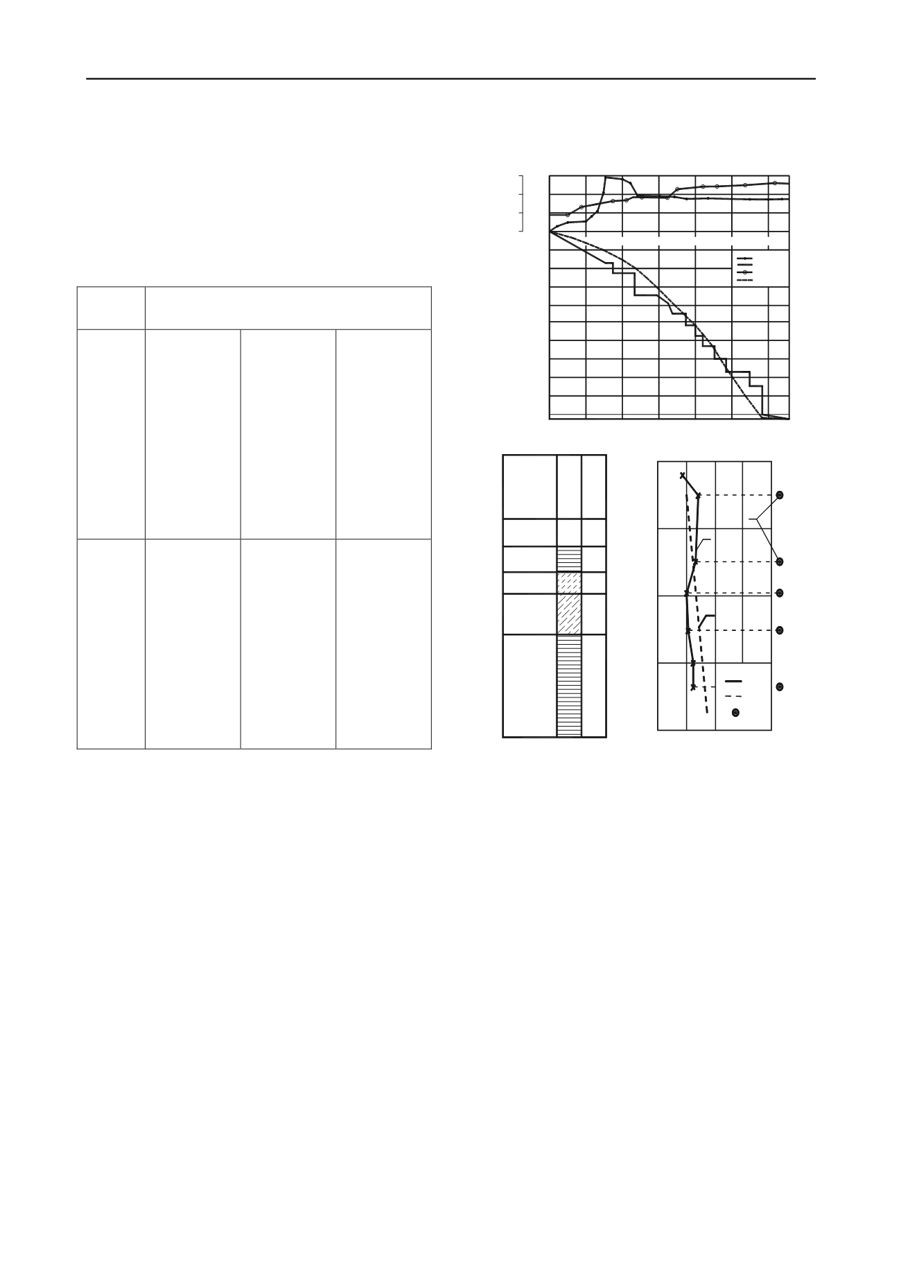
Figure 1 shows the monitoring results for the
construction of a large sunk well using the method of PSTU
(Perminov N.A., Lombas S.V., 2004).
a)
40
30
20
50
10
0,0
м
0,4
0,8
1м
0
25
40
кН *10
5
ия (Н)
4
8
12
16
20
24 мес
П
ения (Т)
родолжительность погруж
Immersion duration (T)
Глубина погружен
1
2
3
4
Weight (G)
Careen (ΔН)
Immersion depth (H)
b) c)
Вид
грунта
т.
на
леват.
глинок
пылеват.
ина
еват.
е
0.2 0.4 0.6 0.8
p (MPa)
5
6
20.00
30.00
40.00
50.00
1.02
0.97
0.83
1.14
1.21
7
- 7
- 6
- 5
Обозначени
Песок
пылева
Гли
пы
Су
Гл
пыл
7,10
5,00
5,10
9,05
25,20
Сугли
пы
нок
леват.
Notations
Type of
soil
dust sand
dust
bluestone
sandy loam
sa
lo
ndy
am
du
bl
st
uestone
Figure 1. The monitoring results for the immersion of a large sunk
well:
a) motiongramm of immersion; b) engineering and geological
conditions; c) monitoring data
1 – diagram of vertical misalignment (careen); 2 – diagram of
immersion; 3 – weigh of the well shell; 4 –ditch bottom; 5,6,7 –
correspondingly, calculated, averaged and peak values of lateral soil
pressure.
The stresses in the reinforcement and concrete were
measured using primary device string type PSAS and PLDS.
To determine the soil pressure membrane load cells with a
range of 0 to 12MPa and measurement error of 5-7% were
used. The measurement was done both in the discrete and
continuous mode using the local electronic switches (LEC),
and data storages (END).
Analysis of monitoring data of large sunk wells with
diameters from 50 to 66m and a depth of immersion of 55 to
71m shows (see Figure 1) that in the process of immersion in
the soils with different strengths and asymmetric structures
deviation from the vertical axis (careen) is observed, with a
shift of the center up to 1.5-1.8 m. In this case, according to
an automated continuous monitoring, as a result of abrupt
landings (breakdowns) stresses in the reinforcement, concrete
and soil pressure may exceed the calculated and the average
values (according to the discrete measurements) 12-15 times.
To estimate the stress-strain state of the well shell with a
sharp landing (breakdown) numerical modeling was
conducted. In the calculations the finite element method
(FEM) and the software package Robot Professional 2010
were used. The calculation is carried out for spatial shell with


