41
Honour Lectures /
Conférences honorifiques
Proceedings of the 18
th
International Conference on Soil Mechanics and Geotechnical Engineering, Paris 2013
under a constant axial rate of 0.5%/hour, punctuated by seven
constant stress creep pauses.
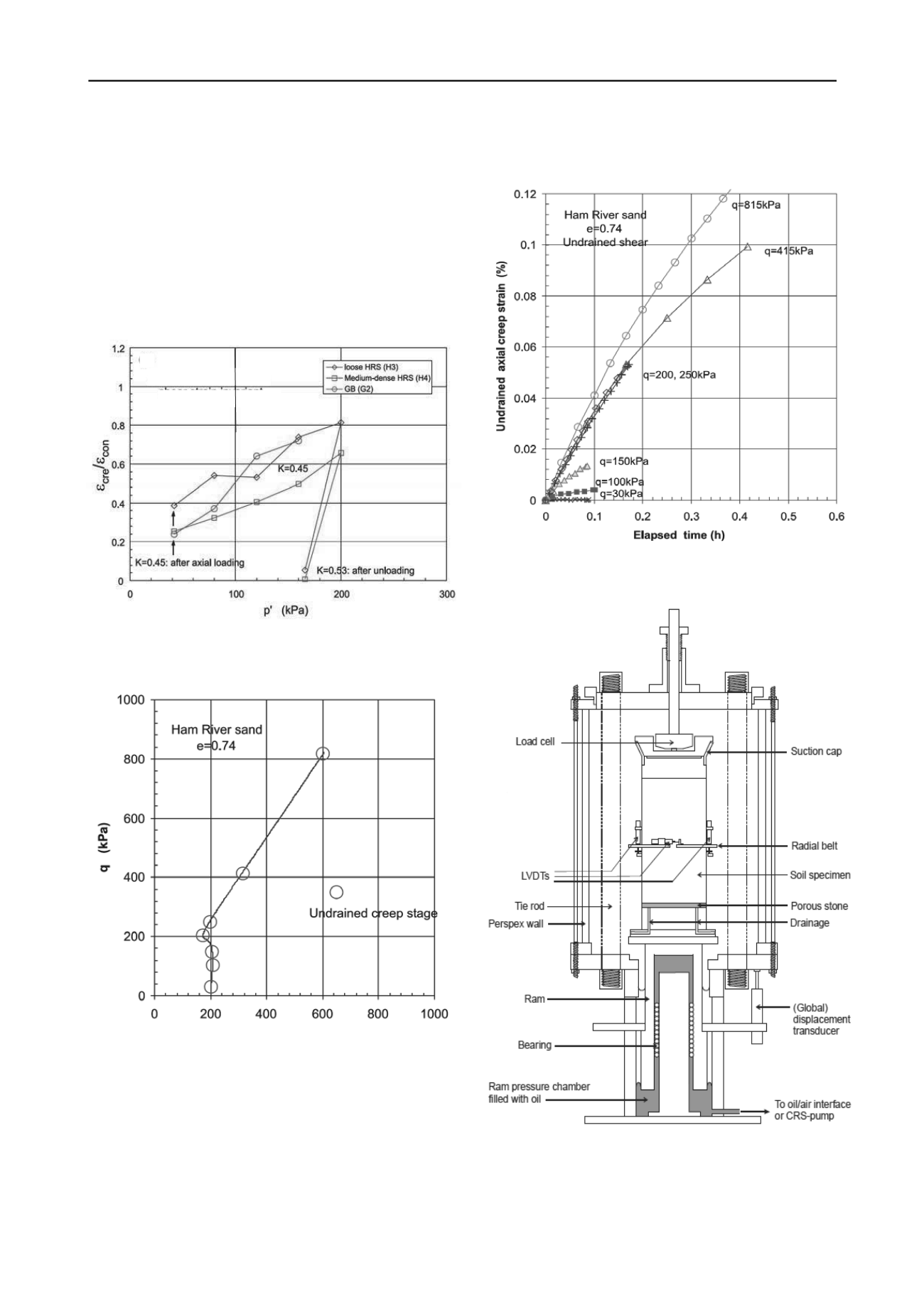
Figure 15 presents the strain-time (ε – t) responses observed
over the undrained creep stages. Note: (i) very little creep before
the Y
2
surface is engaged (at q ≈ 30 kPa ≈ 0.15p΄) (ii) the post
Y
2
family of ε – t curves in which creep rates grow exponentially
with q (iii) a marked softening of the stress-strain response and
anti-clockwise effective stress path rotation at the Y
3
stage
(when q ≈ 160 kPa), (iv) the Y
4
Phase Transformation Point (at q
≈ 200 kPa, p΄ ≈ 170 kPa when q/p΄ approaches M
critical state
) and
(v) a second family of ε – t curves applying post Y
4
showing
creep rates that grow slowly as q increases very significantly.
Fig. 13. Ratios of creep strains ε
cre
to total consolidation axial strains ε
con
in K
0
compression tests on HRS and GB specimens following paths
shown in Fig. 11: Kuwano and Jardine 2002a
p΄ (kPa)
Fig. 14. Effective stress paths followed in undrained ‘Creep’ stress-path
test H2 on HRS specimen: Kuwano and Jardine 2002a
The triaxial trends bear out the pile load-test trends in Fig. 1
for ‘creep-yielding’ (noted at Q ≈ 1 MN with the R piles)
followed by creep rates that rise rapidly with each subsequent
load step. It is clear that time-dependency has an important
impact on both laboratory and field pre-failure behaviour.
We consider next longer-term triaxial stress path
experiments designed to investigate the interactions between pile
ageing and low-level cyclic loading noted by Jardine et al 2006.
Rimoy and Jardine 2011 report suites of tests conducted on
medium-dense TVS sand (see Fig. 4 and Table 1) in the
advanced hydraulic stress path cell system illustrated in Fig 16.
Fig. 15. Strain-time paths followed in seven undrained ‘Creep stages’ of
stress-path test H2 on HRS specimen indentified in Fig. 14: Kuwano and
Jardine 2002a
Fig. 16. Advanced IC automated hydraulic stress-path triaxial apparatus
and instrumentation for 100mm OD specimens described by Gasparre et
al 2007 and employed by Rimoy and Jardine 2011


