51
Honour Lectures /
Conférences honorifiques
Proceedings of the 18
th
International Conference on Soil Mechanics and Geotechnical Engineering, Paris 2013
invariant effective stress paths nor Mohr circles of stress can be
drawn. Shen 2013 presents new DEM based simple shear
simulations. His analyses, which did not require any assumption
of idealised co-axial (or other) plasticity in the sand, emphasize
the differences between the true internal stress variables and the
‘average’ stresses deduced from boundary measurements. He
also highlights the impact of apparatus details on the parameters
interpreted by alternative simple shear failure hypotheses.
Shibuya and Hight 1987, Menkiti 1995, Nishimura 2006 and
Anh-Minh et al 2011 outline the principles and technicalities of
conducting SS tests with HCA equipment. While HCAs are
subject to sample curvature effects that have to be considered
(Hight et al 1983), their annular geometry automatically provides
the complementary shear stresses and so reduces stress non-
uniformity. They also allow the full stress and strain tensors to
be defined and permit detailed assessments of the effects of
anisotropy, variable b values (reflecting σ
2
ratios or Lode angles)
and principal stress axis rotation.
Undrained triaxial experiments can also provide useful
information. The shear stress changes Δ
rz
developed on the pile
shaft pile and changes to triaxial deviator stress Δq = Δ(
1
-
3
)
can be inter-related by assuming an isotropic soil response and
applying general stress invariants, or by simply noting that in a
Mohr circle analysis increments of pure shear shaft loading Δ
rz
have an equivalent effect to an increment Δq that is numerically
twice as large. In this simplified view, the changes to mean
effective stress, Δp' observed under cyclic loading in the triaxial
cell can be seen as implying approximately equivalent
proportional Δ
'
r
changes at points close to the shaft.
Sim et al 2013 emphasize the need for very stable high
resolution test equipment and stable environments for such tests.
This applies particularly to long duration, low-level cycling tests
where p΄ drift rates and changes in cyclic stiffness/permanent
strain development may be slow. Sim et al also report cyclic
experiments on Dunkerque and NE 34 sands designed to help
interpret the field and laboratory CC model pile tests. Their on-
going research programme is investigating:
Differences between HCA SS and triaxial responses.
Effects of pile installation stress history, including the ‘over-
consolidation’ that takes place as the tip passes and the
effects of the shearing cycles imposed by jacking or driving.
The sequence in which different cyclic load packets are
applied, assessing the applicability of Miner’s rule.
Varying sand types and initial sand states.
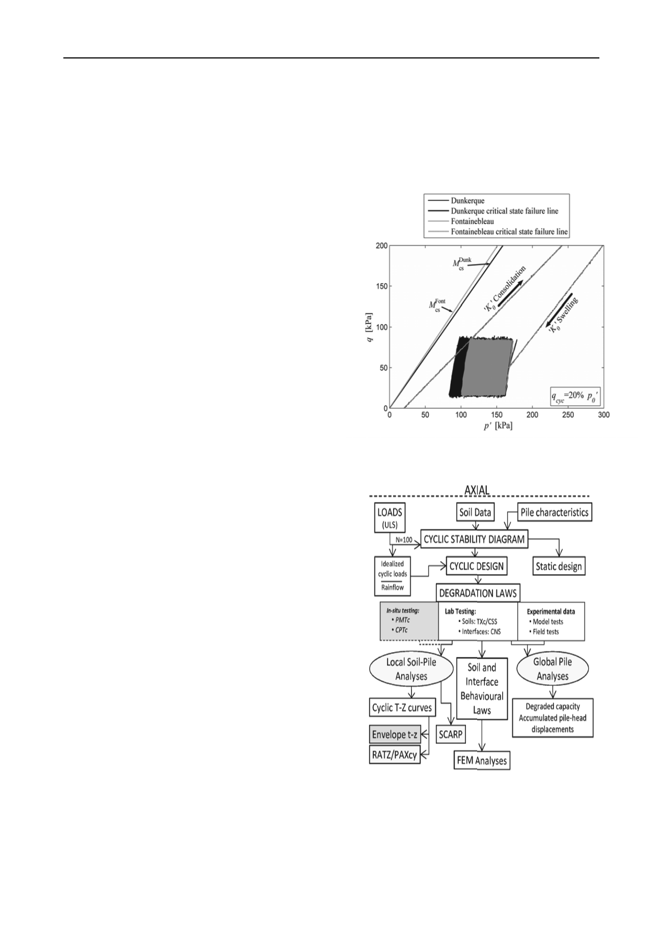
Figure 47 illustrates the leftward effective stress path drifts
developed in undrained cyclic triaxial tests with paired tests on
medium-dense Fontainebleu and Dunkerque samples conducted
after K
0
consolidation to 800 kPa and unloading to OCR = 4, to
simulate pile installation for points positioned 2 < r/R < 3 from a
pile shaft. 1500 q
cyclic
= 0.20p΄ stress controlled cycles were then
applied at 1/per minute. The stress paths evidently engaged the
samples’ Y
2
surfaces. Slow migration led to final mean effective
stress reductions of 30 and 40% overall for NE34 and
Dunkerque samples respectively under the stringent constant
volume conditions imposed. It is interesting that the effective
stress paths remained within the Mini-ICPs τ/σ΄
n
< tan δ΄
interface shear envelope (δ΄ = 27
o
when shearing against NE 34
or Dunkerque sand, see Figs. 34 and 42-45) implying that while
shaft failure would not be expected to reduce in an equivalent
cyclic pile test, the pile shaft would not fail within 1500 cycles.
Jardine et al 2005b and 2012 offer guidance on how to apply
such laboratory testing to estimate the axial response of offshore
piles under storm cyclic loading. Referring to the flow chart
given in Fig. 48, the first essential step is careful characterisation
(applying rainfall analysis methods) of the storm loads to
establish equivalent batches of uniform cycles. Initial screening
checks are then recommended with experimentally derived (or
appropriately validated theoretical) published cyclic failure
interaction diagrams (such as those in Figs 3 or 41). If further
analysis is warranted, laboratory or field test data can be applied
in site-specific and storm-specific calculations that follow either
a local (T-Z, the left hand path in Fig. 48) or a global (the right
hand route in Fig. 48) assessments procedure. The global
approach is most applicable when soil conditions are relatively
uniform and progressive top-down failure is not a major concern.
Fig. 47. Leftward migration of effective stress paths over 1500
undrained q
cyclic
= 0.2 p΄ cycles. Triaxial tests on Dunkerque and
NE 34 sands from p΄
0
= 150 kPa, OCR = 4: Sim et al 2013
Fig. 48 Flow chart outlining approaches for assessing cyclic
loading effects in driven pile design: after Jardine et al 2012.
Jardine et al 2012 describe several approaches for such
calculations. These include the simple ‘ABC’ formulation given
by Jardine et al 2005b. Calibration of the latter approach against
both laboratory tests and the Dunkerque field experiments
indicated encouraging agreement; Jardine and Standing 2013.


