50
Proceedings of the 18
th
International Conference on Soil Mechanics and Geotechnical Engineering, Paris 2013
Proceedings of the 18
th
International Conference on Soil Mechanics and Geotechnical Engineering, Paris 2013
0
100 200 300 400 500
-200
-100
0
100
200
Direction of
radial stresses
'
=27
o
Shear stress
rz
(kPa)
Radial stress
'
r
(kPa)
Leading A
Following B
Trailing C
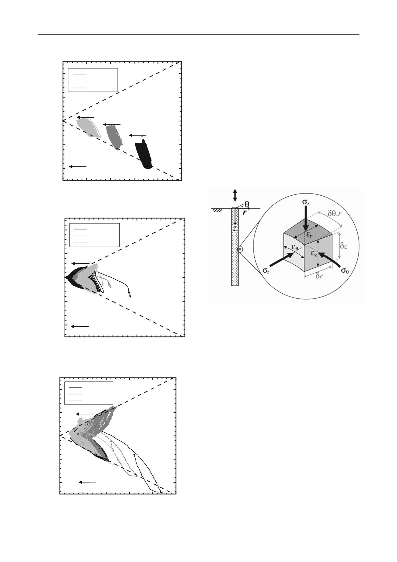
Fig. 43. Interface shear τ
rz
- σ΄
r
effective stress paths: Metastable cyclic
test ICP2-OW3: Tsuha et al 2012.
0
100 200 300 400 500
-200
-100
0
100
200
Direction of
radial stresses
'
=27
o
Shear stress
rz
(kPa)
Radial stress
'
r
(kPa)
Leading A
Following B
Trailing C
Fig. 44. Interface shear τ
rz
- σ΄
r
effective stress paths: Metastable
becoming Unstable cyclic loading test ICP4-TW1: Tsuha et al 2012
0
100 200 300 400 500
-200
-100
0
100
200
Direction of
radial stresses
'
=27
o
Shear stress
rz
(kPa)
Radial stress
'
r
(kPa)
Leading A
Following B
Trailing C
Fig. 45. Interface shear τ
rz
- σ΄
r
effective stress paths: Unstable cyclic test
ICP2-TW1: Tsuha et al 2012
Tsuha et al 2012 report on the similarly in-elastic cyclic local
effective stress responses measured by the multiple cells
positioned in the surrounding sand mass, relating these to the
sand mass failure criteria established by the experiments outlined
in Fig. 37.
9 LABORATORY ELEMENT TESTS TO INVESTIGATE
CYCLIC LOADING PROCESSES
Predictions can be made through cyclic soil element testing of
how cyclic pile head loading affects the local shear stresses
rz
available on the shaft and shear strains in the surrounding soil;
Jardine 1991, 1994. Considering the conditions applying close to
axially loaded shafts, as in Fig. 46, the hoop strain
must be
zero due to symmetry. Also
z
must be
small if the pile does not
slip against the shaft and the pile is relatively stiff. The only
significant normal strain components are radial (
r
) and these are
constrained by the radial stiffness of the surrounding sand mass.
Fig. 46. Soil element adjacent to a pile shaft: Sim et al 2013
The changes in local radial stress,
'
r
, developed on the shaft
in response to Δ
rz
increments that cause dilative or contractive
radial displacements
r at the interface can be related to the
shear stiffness of the surrounding sand by the elastic cavity
expansion expression given as Eq. 6; Boulon and Foray 1986.
Jardine et al. 2005b suggest that
r is approximately equal to the
peak-to-trough centreline average roughness of the pile surface
under static loading to failure. Provided that strains remain very
small and the shear stiffness is linear, Eq. 6 implies a Constant
Normal Stiffness (CNS) interface shear boundary condition,
where
K
CNS
is the interface’s global radial stiffness value.
δσ΄
r
/δr = 2G/R = K
CNS
Eq. 6
Laboratory shear tests can be conducted under CNS
conditions (Boulon & Foray, 1986 or Dejong et al 2003) to
mimic the pile loading boundary conditions and observe the
near-shaft cyclic soil response. Suitable mixed boundary
conditions can be devised for simple shear, triaxial or HCA tests.
However, sands’ shear stiffnesses are non-linear, pressure
dependent and anisotropic. Also K
CNS
varies with 1/R, making it
hard to define meaningful single CNS values. Constant volume
tests in simple shear, triaxial or HCA cells provide upper limit,
infinite, CNS conditions that can be met by cycling saturated
samples under undrained conditions. More sophisticated controls
can be imposed if reliable information is available about the
interface stress and strain boundary conditions.
Constant volume or CNS Simple Shear (SS) tests provide
conditions analogous to those near pile shafts; Randolph and
Wroth 1981. However, conventional simple shear tests cannot
provide a full description of the sample’s stress state: neither


