43
Honour Lectures /
Conférences honorifiques
Proceedings of the 18
th
International Conference on Soil Mechanics and Geotechnical Engineering, Paris 2013
0.00
0.05
0.10
0.15
0.20
0.25
0.30
0.35
0.00 0.05 0.10 0.15 0.20 0.25 0.30 0.35
Volumetric strains (%)
Shear strains invariant (%)
qcyc/p' = 0.05 p'=600kPa
qcyc/p' = 0.025 p'=600kPa
qcyc/p' = 0.015 p'=600kPa
Pure creep at p' = 600kPa
Pure creep at p' = 400kPa
Pure creep at p' = 200kPa
Yield points
Ko line
Fig. 21. Shear strain invariant-volume strain trends followed in creep-
cyclic interaction stress-path triaxial tests on TVS specimens: Rimoy and
Jardine 2011
5 ESTABLISHING
THE
STRESS
CONDITIONS
DEVELOPED AROUND LABORATORY MODEL
DISPLACEMENT PILES
The laboratory element testing described above reveals highly
non-linear, anisotropic, time-dependent and in-elastic stress-
strain behaviour. These features depend critically on the
samples’ effective stress states and stress histories. However, the
lack of knowledge regarding the effective stress regime set up in
the surrounding sand mass when piles are driven called for
further research. Calibration Chamber experiments offered the
promise of new insights that would help to link laboratory
element tests and field pile behaviour.
Laboratory Calibration Chambers (CC) were developed
originally to aid field SPT and CPT interpretation in sands.
Multiple test series have been conducted on uniform (well-
characterized) sand masses under controlled pressure or
displacement boundary conditions; see for example Baldi et al
1986 or Huang and Hsu 2005. Laboratory CCs also provide
scope for measuring stresses in soil masses around model piles
(during and after installation) and also allow ‘post-mortem’ sand
sampling; these activities are far more difficult to perform in
field tests.
Joint research with Professor Foray’s group at the Institut
National Polytechnique de Grenoble (INPG) has included a
comprehensive study of the stresses developed around closed-
ended displacement piles. Cone-ended ‘Mini-ICP’ stainless-
steel, moderately rough (R
CLA
≈ 3μm) piles with 18mm radii R
(the same as a standard CPT probe) were penetrated 1m into dry,
pressurized,
and
highly
instrumented
medium-dense
Fontainebleau NE 34 silica sand. NE 34 has the index properties
shown in Fig. 4 and Table 1 and is broadly comparable to the
earlier discussed Dunkerque, HRS and TVS sands. Jardine et al
2009 detail the general experimental arrangements outlined in
Fig. 22. Cyclic jacking, with full unloading between strokes, was
imposed to simulate pile driving installation.
The Mini-ICP instrumentation included reduced-scale
Surface Stress Transducers that measure radial and shear shaft
stresses at radial distances r/R = 1 from the pile axis at three
levels, as shown on Fig. 23. Measurements were also made of
σ΄
z
, σ΄
θ
and σ΄
r
at two to three levels in the sand mass at radial
distances between 2 and 20R from the pile axis using miniature
soil sensors. Zhu et al 2009 focus on the sensors’ calibrations
and performance, emphasizing the care needed to address non-
linear and hysteretic cell action.
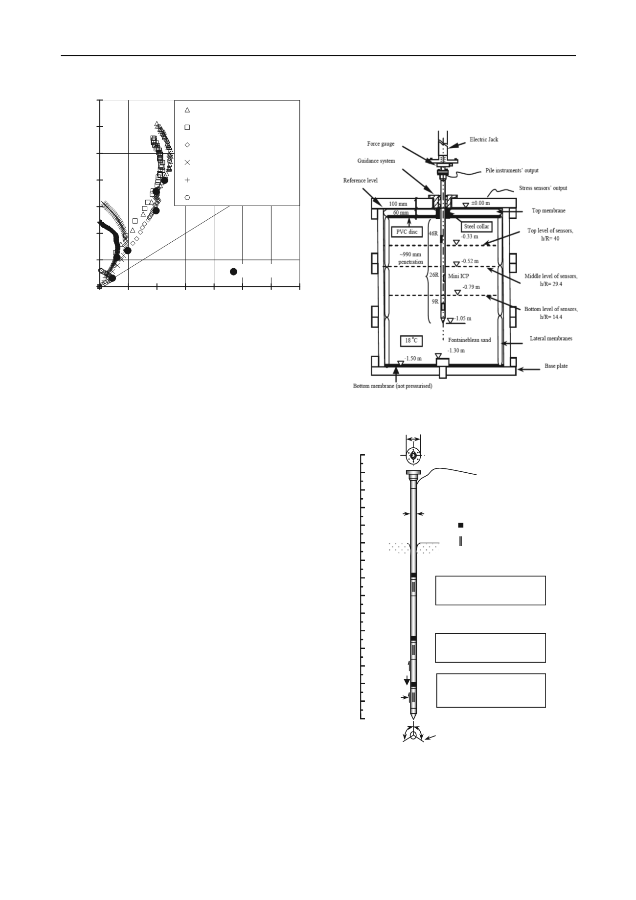
Fig. 22. Schematic arrangements for fully instrumented environmentally
controlled Calibration Chamber Mini-ICP tests: Jardine et al. 2009
10
Fig. 23. Schematic of laboratory Mini-ICP pile with three levels
of Surface Stress Transducers, as well as Axial Load Cells,
temperature sensors and inclinometers: Jardine et al 2009
Upper annular membranes were used to apply a surcharge
pressure of σ΄
zo
≈ 150 kPa to the sand mass. Separate CPT tests
established
q
c
profiles for various boundary conditions. As
shown in Fig. 24, two alternative membrane designs gave quasi-
0
100
200
300
400
500
600
700
800
900
1000
1100
1200
1300
1400
1500
Distance from pile tip,
h
(mm)
Axial load
Surface stress transducer
1
1
d
Trailing cluster
Following cluster
Leading cluster and
Pile tip


