311
Technical Committee 101 - Session II /
Comité technique 101 - Session II
Proceedings of the 18
th
International Conference on Soil Mechanics and Geotechnical Engineering, Paris 2013
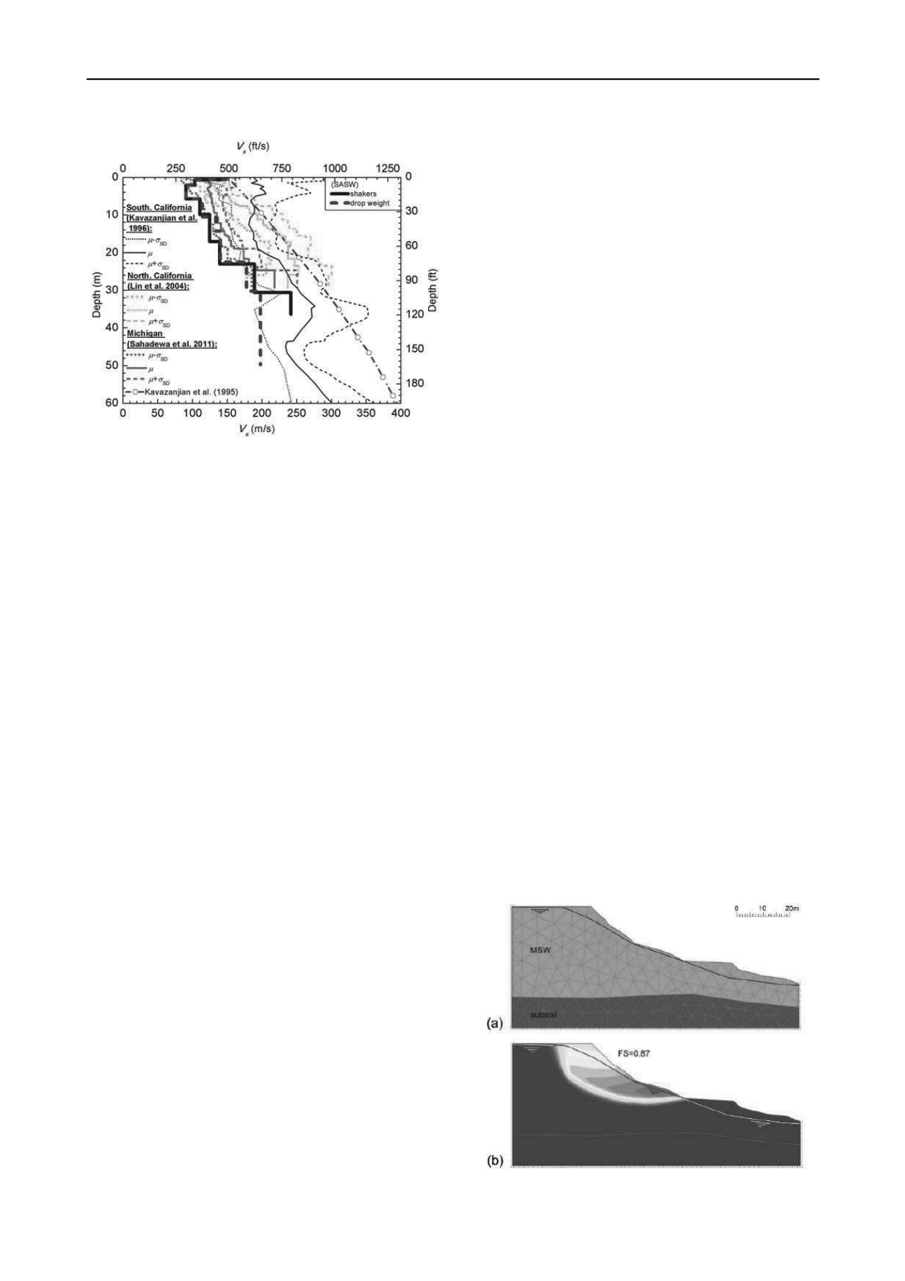
Figure 4. Comparison of V
S0
vs depth profile at Xerolakka landfill with
other published cases of landfills.
5 PROPERTIES OF MUNICIPAL SOLID WASTE
No site specific data was available on the MSW that was
disposed of at the Xerolakka landfill. Thus, for the performance
of the limit equilibrium and finite element stability analyses, the
measured V
S0
was used to guide the selection of MSW
properties. For the performance of the analyses the unit weight,
shear strength, deformation modulus (for the finite element
analyses) and Poisson’s ratio of MSW are required and were
selected as follows:
Unit Weight
: The selection of the MSW unit weight has an
impact on the stability of the waste mass. On the basis of the
available landfill information and the Zekkos et al. (2006)
recommendations, for the 30 m thick waste mass, an average
unit weight value of 12 kN/m
3
was used. This value is also
consistent with the unit weight value used for the design of the
landfill facility (Koronis 1995).
Shear Strength
: The selection of appropriate shear strength
parameters is critical in evaluating the stability of the waste
mass. Bray et al. (2009) recommended a generic MSW shear
strength envelope. The recommended strength envelope was the
mean fit to a large dataset, however, various factors such as
waste composition and unit weight may result in variations from
this envelope. For example, the unit weight has an important
impact on the shear resistance of MSW. As reported by Zekkos
et al. (2010), for waste with the same waste composition, a
reduction in unit weight by 2kN/m
3
results in an approximate
reduction in shear strength by 20%. Considering the absence of
compaction and daily soil cover as well as the particularly low
measured shear wave velocity of the MSW, the shear strength
of the Xerolakka landfill MSW was reduced by 20% from the
shear strength envelope recommended by Bray et al. (2009).
MSW elastic modulus and Poisson’s ratio
: The large-strain
elastic modulus E
ref
is an explicit input parameter in finite
element analysis. The value of E
ref
impacts the calculated
displacements, but does not influence significantly the
calculated factor of safety. In the present study, it was assumed
that the modulus is equal to 1/10 of the small-strain elastic
modulus E
o
, which was calculated from the measured small
strain shear modulus G
o
, whereas the Poisson’s ratio value was
assumed to be equal to 0.1, based on data available in the
literature (Zekkos, 2005).
6 STABILITY ANALYSES
Stability analyses of the Xerolakka landfill slope failure were
performed using both limit equilibrium (Geo-Slope 2007 –
SLOPE/W) and finite element (PLAXIS, 2004) analyses and the
material properties described earlier. Each analysis
methodology has its strengths and limitations. In finite element
analyses, there is no requirement to predefine candidate failure
surfaces; instead, the failure surface with the lowest factor of
safety is identified using the phi-c reduction methodology
(PLAXIS, 2004). Another known advantage of the FEM is its
ability to calculate displacements in every prescribed stage of
calculation as well as its ability to model progressive failure. In
limit equilibrium methodology, the factor of safety for a large
number of failure surfaces is calculated and the one with the
lowest factor of safety is the critical one. For the calculation of
the factor of safety, the Spencer method (Spencer, 1967) is
used. Limit equilibrium methods do not account for the
presence of strain softening materials, since no consideration of
strains or displacements is made.
It is important to note that, in the case of Xerolakka landfill,
it is very difficult to evaluate the actual pore pressure regime
within the waste mass due to the unavailability of field data.
Thus, stability analyses were performed for two cases: complete
absence of leachate table (provided a leachate and gas collection
system was operating properly) and for the case of a high
leachate table resulting from the absence/non operative leachate
and gas collection system. The leachate table used in the
analyses was estimated on the basis of field observations,
namely: 1) the presence of ponding water at the crest of the
landfill (near the waste slide) and 2) observed seepage at the toe
of the waste slide. The high leachate table is intended to account
in a conventional manner for the presence, and possibly flow, of
leachate and more importantly the generation of gas due to
biodegradation. The amount of gas generated can be significant
and for that reason, modern landfill facilities are equipped with
a gas collection system that collects the gas and either combusts
it using a flame or uses it to generate energy. There was no gas
collection system in the active waste disposal area. Gas and
leachate pressures would result in a reduction of the effective
stress in the waste and a subsequent reduction in the factor of
safety.
7 RESULTS OF ANALYSES AND DISCUSSION
Analyses were performed for the selected properties and the
cross-section geometry at the location of the failure. The
inclination of the slopes in the upper part of the landfill is as
high as 1.2:1 (horizontal to vertical). In the case of absence of
leachate table and gas pressure (“dry tomb” landfills), the
results of analyses indicate a stable condition with a calculated
factor of safety equal to 1.60, i.e., higher than the 1.50 typically
required. Additional analyses were performed with the assumed
leachate table, as shown in Fig. 5.
Figure 5. Finite element mesh (PLAXIS 8.6) of the critical failure
surface with (a) soil stratigraphy and (b) critical failure surface for the
estimated leachate table.


