310
Proceedings of the 18
th
International Conference on Soil Mechanics and Geotechnical Engineering, Paris 2013
Proceedings of the 18
th
International Conference on Soil Mechanics and Geotechnical Engineering, Paris 2013
A topographic map of the landfill is shown in Fig. 1. The
first cell of the landfill was geomembrane-lined. Subsequently
the use of geosynthetics was discontinued because of the
presence of impermeable geologic formations (Seisakis and
Roussos, 1994). Due to strong public opposition, new cells
were not constructed, as anticipated in design. In the absence of
an alternative waste management solution, the landfill continued
to receive waste. Thus, a waste mound with increasing height
and slope inclination was formed (shown in the southeast side
of Fig. 1) which partially failed on December 29th 2010.
3 FIELD OBSERVATIONS
On December 29
th
2010, early in the morning (around 08:00
am), a failure of one of the landfill slopes occurred in the active
waste disposal area. The authors performed on-site
reconnaissance at 14:00. The waste slide had plan dimensions of
50 m by 30 m and its crest was located at the top of the landfill
(absolute elevation of +340 m) whereas its toe reached the
access bench 27 m below. The volume of the slided waste mass
is estimated to be equal to 12,000 m
3
. The waste slide debris
covered one of the landfill benches that was used as access road
to the active waste disposal area, thus disrupting landfill
disposal operations. During the reconnaissance visit, the waste
that covered the access road was already partially removed and
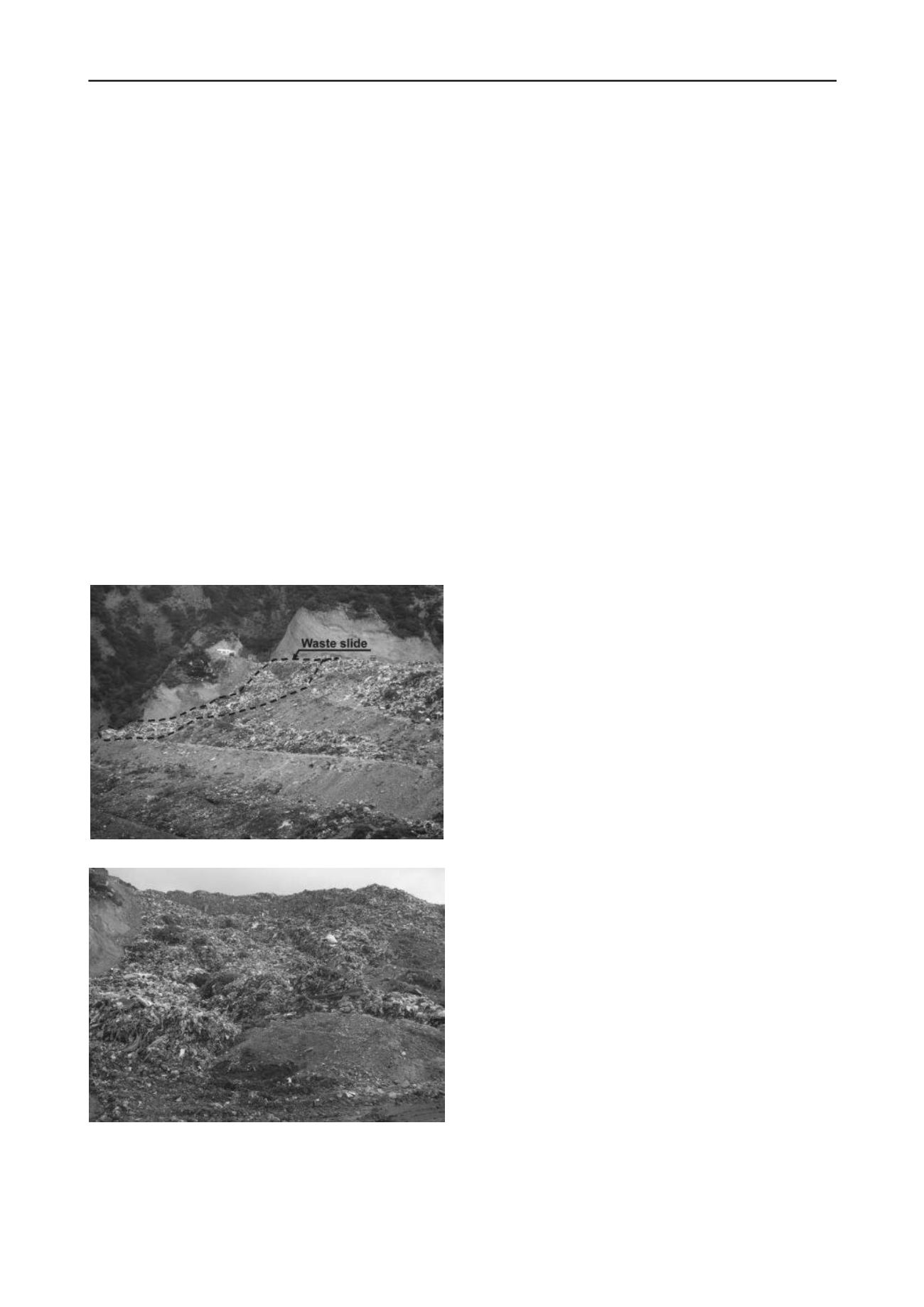
pushed downhill. A view of the slide from the West is shown in
Fig. 2 and a view of the slide from its toe after removal of the
waste from the landfill access bench is shown in Fig. 3.
Figure 2. Waste slide view from the western side of the MSW landfill.
Figure 3. Waste slide view from the access bench located at the toe of
the slide.
The waste slide is located adjacent to the graded canyon
slopes with the Northeast portion of the slide exposing the
native rock mass (also shown on the left side of Fig. 3).
Precipitation on the steep canyon slopes in the vicinity of the
waste slide drains towards the waste mass due to the absence of
surface water cutoff drainage ditches and percolates in the
waste.
The uppermost layer of MSW in the active waste disposal
area (i.e., the landfill crest) was not compacted and did not
include any daily soil cover. The compaction of waste had
reportedly ceased for at least a year prior to the failure and daily
soil cover was not used for many months, possibly years. The
absence of daily soil cover on the top waste layers can be seen
at the right side of Fig. 2. In addition, the gas collection system
was not operational.
The crest of the landfill was not graded properly to manage
surface water runoff due to precipitation and in the vicinity of
the failure slide mass, rainfall water was found to be ponding.
Leachate was observed to pour from the toe of the waste slide
whereas an interceptor trench that was built next to the landfill
bench was also found to contain leachate. Media photos from
earlier in the morning of the 29
th
of December indicate a large
wet area in the vicinity of the failure, apparently from liquids
that came out of the waste mass.
The December 29
th
2010 failure occurred four days after a
rainfall event. A weather station located in the Port of Patras at
a distance of 4.5 km away from the landfill and at an absolute
elevation of +6 m, recorded approximately 11 mm of
precipitation for that event and a total of 16.5 mm in the five
days prior to the failure. Ten days earlier, another event with a
precipitation of 20 mm occurred. This amount of precipitation is
lower than the corresponding amount of rainfall in the past two
years; however, the geometry (height and inclination) of the
landfill slopes had changed in the last year, adversely affecting
its stability. The complete absence of surface water
management system and daily soil cover, would have allowed
for the rainfall water to easily percolate in the waste mass.
4 FIELD MEASUREMENTS
A high-resolution 3-D topographic map of the landfill area was
generated by performing terrestrial LIDAR (Light Detection
and Ranging) measurements, in addition to conventional
geodetic survey. The measurements utilized land-based laser
scanning technology and allowed a reliable definition of the
failed waste mass. Field measurements of the in situ shear wave
velocity (V
S0
) were also performed. Shear wave velocity is a
critical parameter that has been used to characterize the MSW
(Zekkos, 2011). In this project, V
S0
was used to characterize the
MSW and assist in the selection of values for MSW material
properties. Shear wave velocity profiles were also explicitly
used for the performance of seismic stability analyses that are
not described herein.
The small strain shear wave velocity of waste material was
evaluated as a function of depth by applying the Spectral
Analysis of Surface Waves (SASW) and Refraction
Microtremor (ReMi) techniques. The application of these
techniques is preferred in the case of landfills due to their non-
intrusive nature (Matasovic et al., 2011). The V
S0
vs. depth
profile is shown in Fig. 4.
Fig. 4 compares the V
S0
vs depth profiles measured at
Xerolakka landfill with the data available in the literature. The
mean and mean±sigma V
S0
curves are shown for MSW in three
geographic
regions,
specifically
southern
California
(Kavazanjian et al. 1996), northern California (Lin et al. 2004)
and Michigan (Sahadewa et al. 2011). It is observed that the in
situ data from Xerolakka are in the lower range of the literature
V
S0
data. This difference may be attributed to a number of
factors including waste composition, but more importantly the
absence of waste compaction and daily soil cover. It should be
mentioned that, following the waste slide, the placement of
waste (from Dec. 2011 to May 2012) was carried out in a single
thick lift (~8 m), overlain by a soil cover ranging from 1 to 3 m.


