3354
Proceedings of the 18
th
International Conference on Soil Mechanics and Geotechnical Engineering, Paris 2013
Proceedings of the 18
th
International Conference on Soil Mechanics and Geotechnical Engineering, Paris 2013
some distance from the excavation. This might reduce the draw-
downs in the centre of the pit.
The chosen groundwater lowering system consisted of a
combination of well-points, bored wells and a drainage system
beneath the membrane.
The well-points were closely spaced at approx. 6 meters depth
at the perimeter of the pit to deal with the groundwater flow in
the upper layers of sand.
In addition eight bored wells were placed at the perimeter to
deal with the deeper water built-ups. Besides pumping from the
wells vacuum was applied to the wells to reduce pore water
pressures in the soil and increase the effective stresses in the
soil, at least to some distance from the wells.
Furthermore, a well in the centre of the pit was performed to
prevent uplift. This well was initially installed with a pump, and
during excavation the well was successively cut down to
excavation level and the pump was removed.
Before covering up the bottom and the sides with the
membrane, a drainage system in connection with the (weeping)
well was established in the bottom. To prevent a lifting problem
caused by accumulation of water beneath the membrane,
pumping on the drainage system was made possible by
traditionally well pumps mounted through two installed pipes
laid in inclining ditches up the sides.
Pumping from the drainage system, the well-points and the
bored wells at the perimeter of the pit was sustained until the pit
was filled with water unto the measured highest natural ground
water level approx. 1 meter below the surrounding level.
4.3
Soil handling
The excavated soil had to be built-in in the embankments
around the pit. The soil mainly consisted of clay, where
moisturing/weathering normally must be avoided in order to
obtain reasonable compaction (more than 95 % Standard
Proctor) and confined deformations of the embankments.
Therefore, the earth works must take place during a period with
favourable weather conditions, which in Denmark means the
summer period.
Furthermore, the poor strength properties of the marine clay
of high plasticity
–
especially in a remoulded condition - was
dictating that the clay only had to be rebuilt in areas where the
requirements to the soil were less critical.
4.4
Consequences of thermal influence to the soil
In the operational phase the temperature in the adjacent soil will
increase, maybe up to 90°C close to the pit. This heating of the
soil might cause a drying-up effect of the soil above the ground
water table if no water is added from e.g. precipitation. In the
actual case the clays seemed so preconsolidated that the natural
water content was considered to be close to the shrinkage limit.
Consequently the risk of development of a long term
deformation problem was evaluated as a minor issue.
5 CONSTRUCTION PHASE
The PTES was established during the summer 2011 which
happened to be very wet with precipitation more than twice the
normal precipitation. In addition, a cloudburst occurred with
more than 100 mm precipitation overnight which caused
damages to the just finished surfaces and obstacles for the
subsequent works. Consequently, the construction period was
delayed 3 months into the winter.
This entailed that the preconditions for the project was
severely challenged. Especially the maintenance of the stability
of the sides was alarming. The predicted long term problem
with poor drained strength parameter might be worsened if the
efficiency of the ground water lowering system was reduced
(due to clogging etc.). This problem period was not to end until
the filling-in of water was above the surrounding ground level.
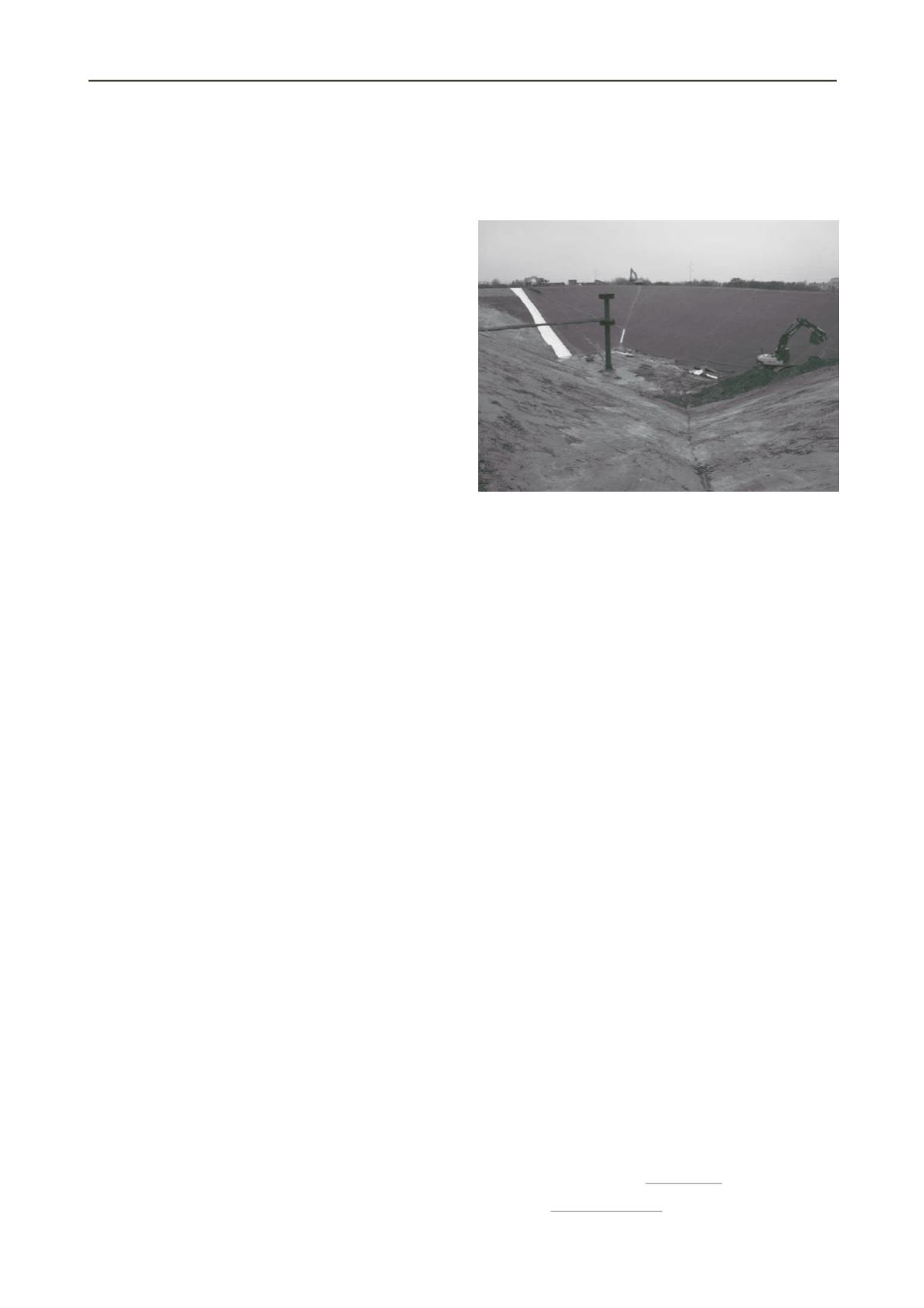
In spite of this no severe ruptures were recorded. Figure 6
shows a photo of the pit at a late stage of the excavation work.
Figure 6. Photo of pit during completion of excavation and laying out of
the membrane in progress. The tower in the centre of the photo is a 16
m tall water in- and outlet for the operational phase of the PTES.
6 CONCLUSIONS AND PERSPECTIVES
The PTES project in Marstal has demonstrated that a thermal
energy storage with 75,000 m
3
water is obtainable in connection
with solar heat based district heating systems. The construction
cost of the Marstal storage was 41
€ per
m
3
of water (exclusive
VAT) including all pipe connection to the plant, control system,
geotechnical support, etc. The construction cost also includes
research and development costs of the storage and different lid
designs. The costs are cost-competitive compared to other
storage systems (e.g. TTES, ATES and BTES) and there is a
potential to bring the costs further down.
The project has encountered difficulties in matters of soil and
ground water conditions and challenges due to circumstances in
the actual climate, but these challenges has been dealt with in
order to minimize the costs of the PTES. Details in the project
still needs to be optimized, but the project is a stepping stone in
the development of the necessary techniques for decreasing the
use of renewable energies.
The aim of the authors of this article is to pinpoint the
challanges to be encountered during planning and execution of a
PTES illustrated by an actual project.
It is the authors’
perception that a PTES is applicable for a lot of sites.
Denmark has approximately 400 district heating plants of
varying size. Most of these plants are placed in rural areas,
where establishment of solar heating plants supplemented by a
PTES is an obvious solution. As an example the planning of a
60,000 m
3
PTES in connection with 35,000 m
2
solar heat panels
at Dronninglund Destrict Heating in Denmark is ongoing and
will presumable be established in 2013 - 2014. Some
PTES’s
have been established in other countries, e.g. Germany, but
none as large as in Denmark.
7 REFERENCES
GEO Danish Geotechnical Institute 2010-2011. Geotechnical reports for
establishment of a PTES in Marstal (not published).
Mangold D, Schmidt T, The next Generations of Seasonal Thermal
Energy Storage in Germany,
Marstal District Heating 2010-2012. Monthly solar heat production and
radiation,
.
Verein Deutscher Ingenieure 2004, 4640 Blatt 4.


