3353
Technical Committee 307 + 212 /
Comité technique 307 + 212
Proceedings of the 18
th
International Conference on Soil Mechanics and Geotechnical Engineering, Paris 2013
excavated pit. The excavated soil must be well suited and
compactable for this purpose.
3 CONSTRUCTION AND SITE INVESTIGATIONS
In Marstal the PTES is placed on the top of a smooth hill in the
outskirts of the town.
Due to area restraints the pit is slightly rectangular and
measures 88 meters by 113 meters at the top, i.e. a bit larger
than a football field. The water depth is 16 meters, of which
approx. 12 meters go below the natural ground level and 4
meters are established by embankments of the excavated soil at
the perimeter. As mentioned above the total volume of water is
75,000 m
3
.
Early in the design process the slope of the sides was chosen
to 1:2 which in a practically view is the steepest possible
inclination for the installation works of the liner. This
corresponds to an angle of 26.6° against horizontal level. Figure
4 shows a stylized cross section of the pit.
Figure 4. Stylized cross section of the PTES in Marstal.
A site investigation has been performed prior to the design
phase. The investigation consisted of 10 borings, of which two
borings in the centre were taken to 25 meters depth and 8
borings at the perimeter of the excavation were taken to 13
meters depth. The borings were performed as traditionally
geotechnical borings with soil sampling, in-situ tests and
installation of standpipes at adequate depths.
The investigation showed a thin layer of top soil covering
various glacial deposits of primarily clay till and glacially
relocated marine clay of interglacial origin (Cyprina Clay). At
the northern side three meters of melt water sand were covering
the clay. Besides, stripes and zones of melt water sand and sand
till were found, apparently randomly in the clay.
In a geotechnical matter the marine clay was of special
interest. The clay was of high to very high plasticity with
plasticity index I
P
≈
50 %. The natural water content was w
nat
=
21
–
30 % close to the plasticity limit. A fissured structure was
detected in several samples, presumably caused by shear
stresses during the glacial period and/or passive earth pressures
at the end of the glacial period.
The clay deposits were generally stiff to very stiff. Field vane
tests showed undrained shear strength c
fv
between 250 and >700
kPa, thus with a slightly softened zone near the surface.
The effective strength parameters in the clay were estimated
from a priori knowledge of similar soils. The characteristic
value of the angle of friction of the marine clay was estimated to
φ ≈ 20° and of the clay till to φ ≈ 30°
with mean values
approximately 5 degrees higher. Some effective cohesion in the
clay must be expected, but according to Danish calculation
practice
the cohesion was limited to c’ = 20 kPa in unfissured
clay and c’ = 0 kPa in fissured
clay (on the safe side for
decreasing stress level).
Standpipes had been installed at differing depths, separated by
bentonite sealing materials. Groundwater levels were measured
at very varying depths between a few meters depth and large
depth (below excavation level). These measurements are
assumed to be variably ground water build-ups depending on
precipitation and season, whereas a stable ground water table in
a primary aquifer is at large depth.
4 CONSIDERATIONS FOR THE CONSTRUCTION
Establishment of a PTES at the actual site was subject to four
geotechnical concerns: the excavation stability, the groundwater
and soil handling during the construction phase and the long
term consequences of thermal influence on deformations in the
operational phase.
4.1
Excavation stability
The stability of the excavation sides was to be sufficient during
the construction phase. Provided that the ground water issue
was handled, it was evident that a quickly performed excavation
and refilling with water would be advisable as the clay would be
stable in the short term undrained condition. On the other hand,
calculations based on long term drained strength parameters
showed unstable slopes in the marine clay, especially when
adding prescribed safety factors according to Eurocode 7.
The period from starting excavation until fully filling the pit
with water was planned to last 6½ months. One month had to be
reserved the liner work, and as the available capacity for filling
the pit with water was limited to 50 m
3
/h the filling would itself
take two months.
Undrained conditions were evaluated to last at least one
month, but exceeding this period by several months caused
severe considerations of the time for developing drained
conditions and consequently collapses due to unstable slopes. It
was evaluated that further tests and evaluations would not
improve this engineering judgement significantly, and therefore
the stability had to be evaluated for drained conditions.
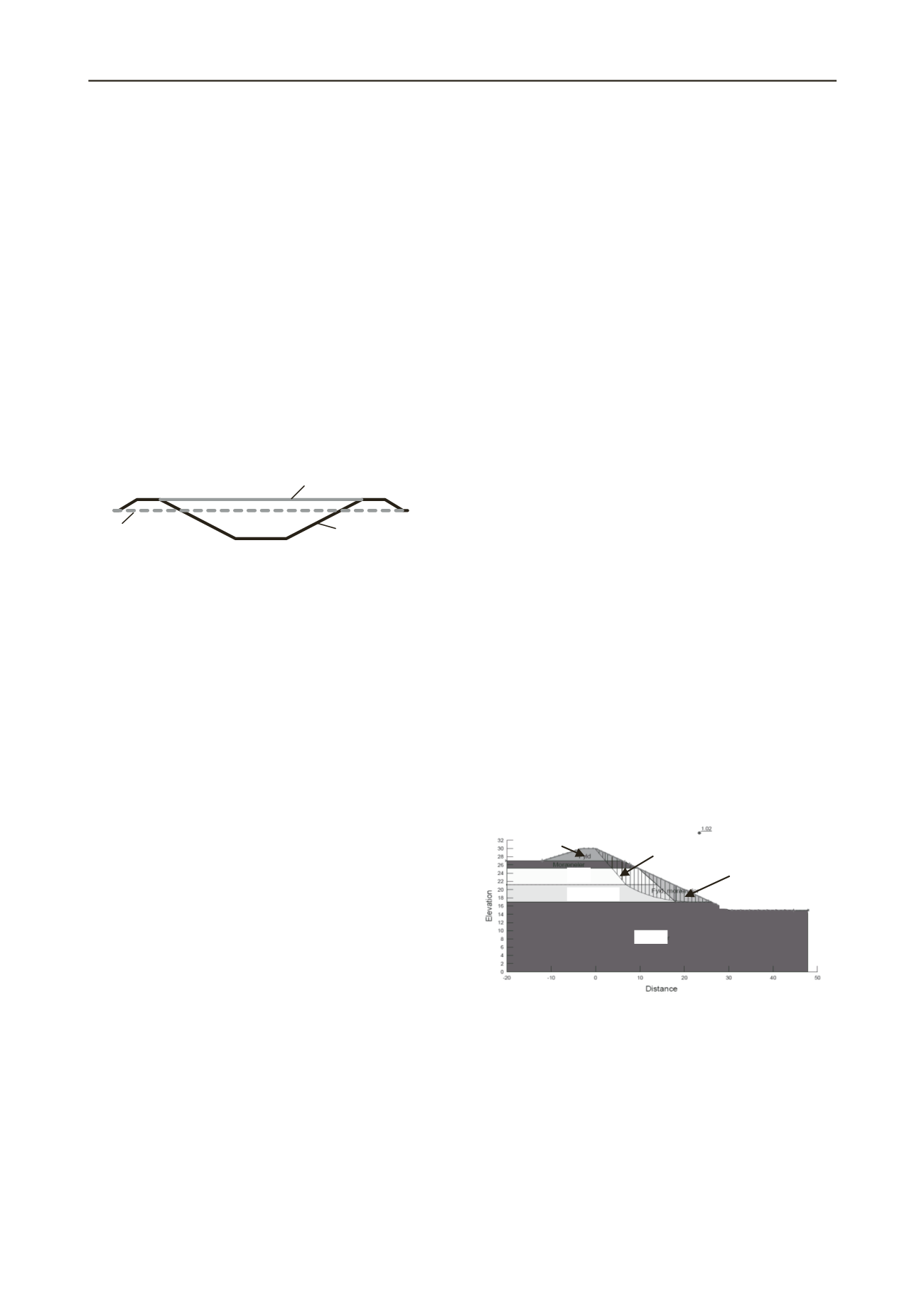
Introducing less steep slopes than 1:2 was not an option, but a
series of slope stability calculations based on different cross
sections showed that it was possible to establish stable slopes of
1:2 by replacing layers of the marine clay until certain depths
with sand or even clay till, see figure 5, forcing the rupture line
at greater depth to involve more stable materials. The
replacement of the marine clay would increase the volume of
soil to be handled in the project by approximately 15 % which
was acceptable.
During the excavation phase it was decided to abstain from
replacements until indications of failures were observed. This
reduced replacements to an absolute minimum.
Figure 5. Example of slope calculations.
4.2
Groundwater handling
The potential energy loss due to groundwater flow across the
site was evaluated to be very limited.
The groundwater build-ups had to be eliminated to enable dry
excavation and a proper handling of the membrane.
Furthermore groundwater lowering was necessary to prevent
uplift, damages due to seepage from the excavation sides and
sliding of the sides, which especially would be problematic if
the sides were sliding after covering with the membrane.
The circumstance that the bottom of the pit was to be covered
with a membrane implied that the groundwater lowering works
was directed to take place on the outer side of the pit, i.e. at
Slope 1:2
Water
Triangle of removed
clay of high plasticity
Rupture line
Fill
Sand
Marine clay
Clay till
Natural ground level
Insulated lid


