3345
Technical Committee 307 + 212 /
Comité technique 307 + 212
HDPE pipes are 0.025 m in diameter and with a 0.003 m wall
thickness. The spiral configuration consists of an inlet pipe with
a 0.3 m spiral major diameter and axial pitches which are
varied, sequentially, between 0.2 m to 1 m; and a straight outlet
pipe (Figure 3-a). Consequently, different pipe lengths are
modelled to investigate the effects on heat extraction rate.
Numerical results obtained from the above modelling are
compared to the results from 0.46 m diameter, 30 m long GHEs
with single, double and triple U-pipes, 0.025 m in diameter
embedded within, which render the same pipe lengths as the
ones in the spiral configurations (see Figure 3-b through -d).
The same assumed constant material properties are shown in
Table 1. The FEM mesh in these model follows the same mesh
density distribution as shown in Figure 2.
(a) (b) (c) (d)
Figure 3. Detail of GHEs with (a) spiral pipe, (b) single U-pipe; (c)
double U-pipe, (d) triple U-pipe.
2.2
Initial and boundary conditions
A depth dependent temperature, varying between 8.7
°
C at the
ground surface and 18.6
°
C for the first 10 m below the ground
surface, is applied over the entire model (the GHEs and the
ground) as initial and far-field boundary condition. Below this
relatively thin layer and from about 10 m to 30 m below the
ground surface, a constant temperature of 18.6
°
C is applied to
the rest of the model. To account for the thermal interaction
between conductive and convective heat transfer, the inlet
temperature and fluid flow rate are also specified as boundary
conditions. The simulations are run in heating mode, that is,
whilst extracting heat from the ground. For simplicity, a typical
inlet temperature of 5ºC is prescribed in the inlet pipe(s) of the
modelled GHEs. For the fluid flow simulation inside the pipes,
a no slip boundary condition is applied on the pipe walls, in
other words, the water velocity on the pipe wall is set to zero;
and a reference atmospheric pressure is set in the outlet pipe(s)
for the purpose of forced convection.
3 RESULTS
In this section a brief summary of the model validation is
presented together with the results of the numerical simulations
of the various ground loop configurations and fluid flow rates.
3.1
Model validation
Numerical results obtained from the transient study of GHE
with a single U-pipe were validated against analytical solutions
that are based on Infinite Line Source Model (ILSM), Finite
Line Source Model (FLSM) and Cylindrical Source Model
(CSM). Details of these solutions can be found elsewhere
(Bernier 2001, Deerman 1990, Jun
et al.
2009, Lamarche and
Beauchamp 2007, Marcotte and Pasquier 2008). As an example,
Table 2 summarises the results in terms of heat extraction rate q
and outlet pipe(s) temperature T
out
for the case of a 30 m long
GHE, with 0.025 m diameter single U-pipe and water flow rate
of
∼
14.5 l/min after 120 hrs of operation. Numerical results are
in good agreement with the FLSM, which is the most reliable
model among the previously mentioned models. The numerical
results are also within the range of measurements reported for
full scale experiments (Banks 2008, Gao
et al.
2008, Hamada
et
al.
2007, Miyara
et al.
2011).
Table 2 Comparison between analytical and numerical solutions.
Parameter
ILSM
FLSM
CSM
Field
data
This
work
q [W/m]
30.67
44.93
32.14
10-60
48.87
T
out
[
°
C]
5.93
6.36
5.97
-
6.48
3.2
Numerical results and discussion
With the numerical model validated for the single U-pipe case,
other GHE pipe configurations were then examined: the double
U-pipe and the double cross U-pipe. Cross sections of all small
diameter GHEs were shown in Figure 1. We studied the effects
on the thermal performance of these GHE configurations caused
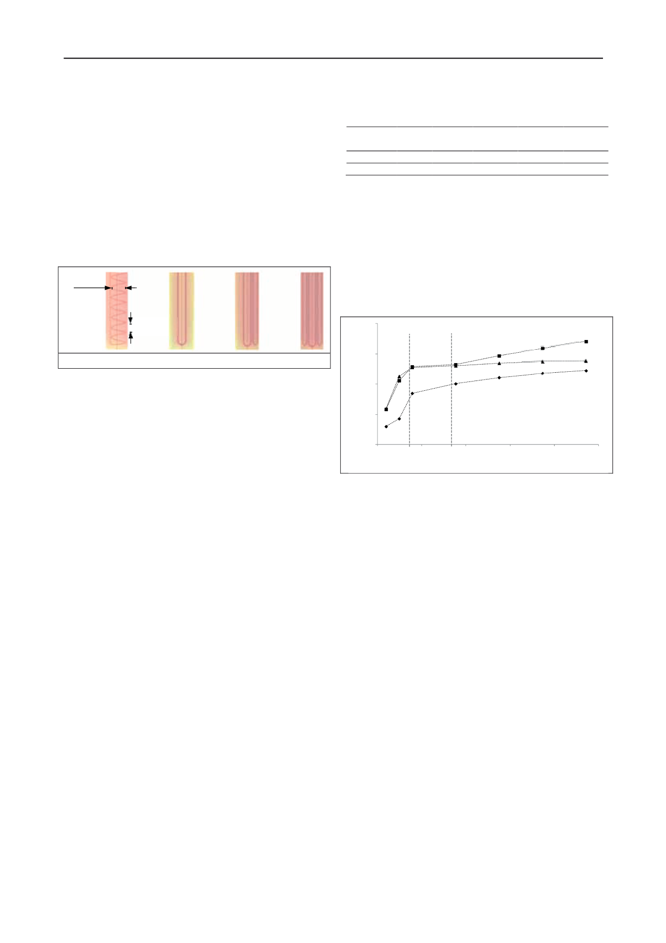
by variations of water flow rate. Figure 4 shows a summary of
the numerical results for GHEs with single, double and double
cross U-pipes, expressed as the total average heat extraction of
each GHE per meter depth of borehole.
Figure 4. Heat extraction rate as a function of fluid flow rate.
As the average water flow rate increases in the pipe, heat
extraction rate first tends to increase at a high rate for all GHE
configurations considered here. However, above a flow rate of
approximately 5.30 l/min (u = 0.18 m/s) the flow becomes
turbulent and the increase in the heat extraction rate with flow
(or Reynolds number) slows down in comparison with the
laminar regime. Thus higher flow rates, do not necessarily
results in significant increase in system’s efficiency and the rate
of increase declines with Reynolds number beyond a certain
threshold. The addition of a second U-pipe to a single U-pipe
configuration does not double the thermal performance but
achieves between about 40% to 90% additional performance,
depending on the volume of the water in contact with the
ground heat source/sink. Nevertheless, savings may be achieved
in terms of drillings costs, given the reduction in the total
number or length of GHEs than would be needed with a single
U-pipe. The comparison of double U-pipe and double cross U-
pipe configurations shows that GHEs with double U-pipe
perform about up to 23% better while the water fluid flow is in
turbulent regime, and has nearly the same performance in
laminar regime, for the pipe separations studied here.
For the case of large diameter GHEs, Figure 5 shows the
effect of axial pitch in GHEs with spiral pipes. The figure shows
that smaller axial pitches, which render longer pipe length,
result in higher thermal performance since there is larger
contact area between the water and the ground heat source/sink.
Comparing the thermal performance between large diameter
GHEs with spiral pipes and U-pipes, Table 3 shows that for a
given total water flow rate of 14.5 l/min in each GHE, and
borehole length and diameter, GHEs with same pipe length
embedded within have nearly the same thermal performance
regardless of pipe geometry specifically when dealing with
more than one U-pipe (i.e., spiral and multiple U-pipes with
0.14 m of pipe separation). Therefore, GHEs with multiple U-
pipes instead of spiral pipes would be recommended, since (i)
installation of GHEs with spiral pipes is, in general, not as easy
0
20
40
60
80
0
3
6
9
12
15
Heatextraction rate [W/m]
Flow rate [l/min]
Transitional
Laminar
Turbulent
Axial
pitch
Major
diameter
Single
Double cross
Double


