3340
Proceedings of the 18
th
International Conference on Soil Mechanics and Geotechnical Engineering, Paris 2013
carried out. Numerical simulations and analytical investigations
were also performed to identify the important parameters that
influence the heat output.
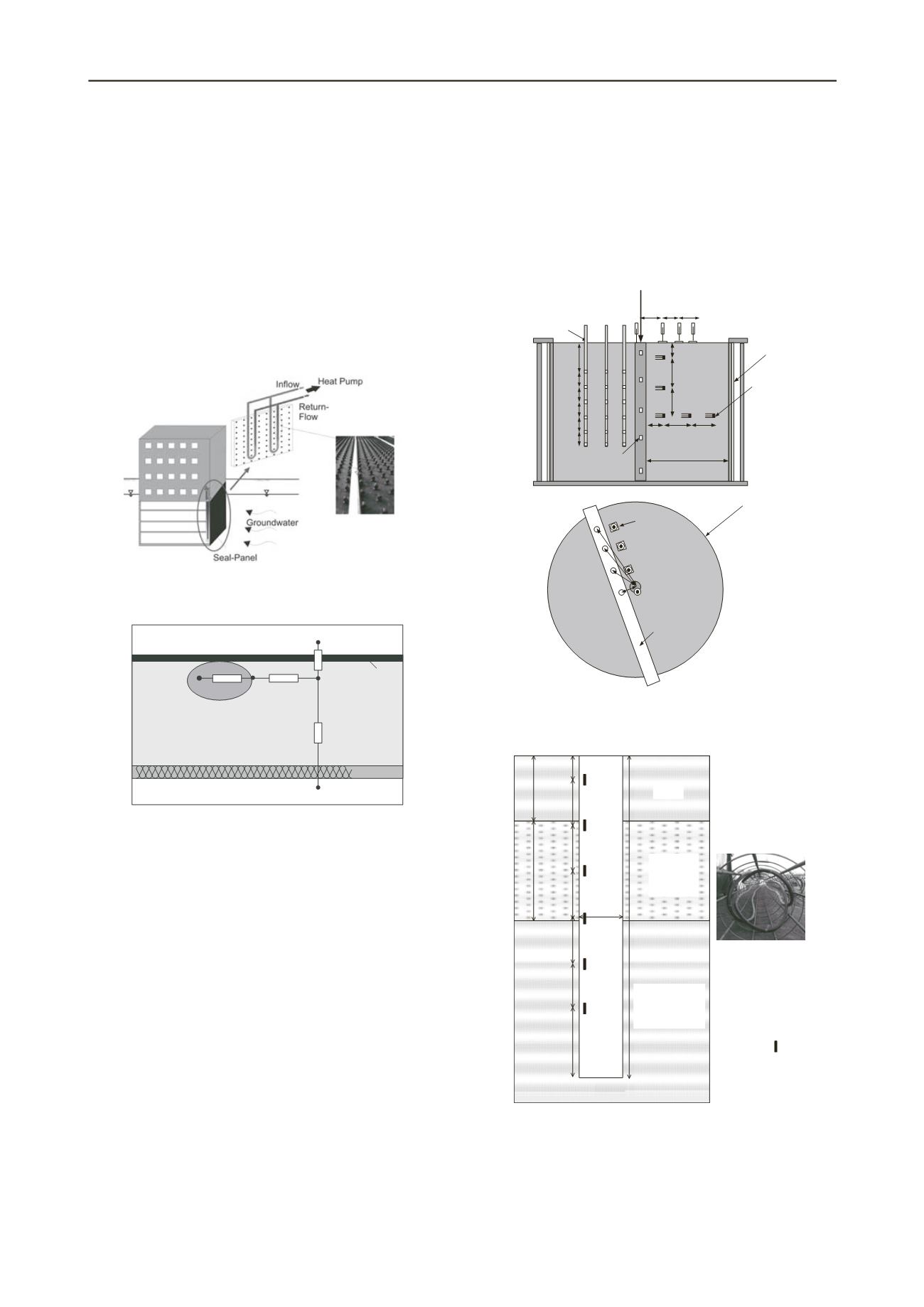
In the second example, Ziegler and Kürten described the use
of thermo-active seal panels with integrated heat-exchange
pipes (Figure 13) used in underground structures in direct
contact with groundwater. The authors tested the efficiency of
the panels through laboratory experiments. They noted the
importance of heat transfer between soil and heat exchanger for
achieving high efficiency. Because both these examples require
plane heat-flow models (instead of axisymmetric models) to
describe the heat flow, Ziegler and Kürten introduced a new
equivalent thermal-resistance model (Figure 14) for describing
heat transfer through plane structures.
Figure 13. Thermo-active seal panel (Figure 2 of Ziegler and Kürten).
Sealing
Concrete
Insulation
Room
T
1
T
2
T
C
T
W
T
m
R
Pipe
R
X
R
W,1
R
W,2
Figure 14. Equivalent star-network thermal resistance model for
thermo-active seal panel (Figure 7 of Ziegler and Kürten).
The problem of energy piles is more complicated than that
of geothermal heat pumps because of the coupled thermo-
mechanical response. The coupled behavior of energy piles is
highlighted in the study by McCartney et al. in which they
investigated the impact of the pile-head boundary condition on
the response of end bearing geothermal piles using a centrifuge
test and monitoring a full-scale pile beneath an 8-story building
at Denver, CO, USA. In the centrifuge test (Figure 15), the pile
had a length of 533.4 mm and a diameter of 25 mm, and the
scaling factor was 24. The pile was maintained at a constant
temperature and then analyzed for thermally induced stresses
and strains with load (no restraint) boundary condition at the
head. The full-scale end-bearing drilled shaft (Figure 16) of
length 14.8 m and diameter of 0.91 m has three heat-exchanger
loops and is restrained at the head due to the presence of grade
beams. The authors recognized the difference in the soil profiles
and boundary conditions of the two piles and concluded that the
boundary condition at the pile head has a significant effect on
the magnitude and shape of stress distributions in energy piles.
Wang et al. also investigated through a field test the impact
of the coupled thermo-mechanical response of energy pile on its
capacity. A full-scale in situ geothermal energy pile equipped
with ground loops for heating and cooling, multi-level
Osterberg cells, thermistors, strain gages and transducers was
installed at Monash University, Australia in an unsaturated, very
dense sand profile. It was observed that the shaft capacity
increased when the pile was heated and returned to its initial
value when the pile was cooled (see Figure 17). The authors
noted that energy piles have the potential to reduce the energy
demand in built structures. They concluded that further research
is required to understand the pile shaft behavior in different soil
conditions and to assess the thermal properties of the energy
pile ground heat exchanger and the surrounding soil for
different field conditions.
Insulation
Thermocouple
profile probes
Strain gauges/
Thermocouples
Building
Load
LVDTs
Support beam
for LVDTs and
thermocouple
profile probes
5.5D
50.8
mm
88.9
mm
76.2
mm
38.1 mm
126.2 mm
102.4 mm
LVDTs
(Surface
deflections)
76 mm
140 mm
216 mm
292 mm
114
mm
38.1
mm
76.2
mm
15.4
mm
30.4
mm
Dielectric
sensors
(water
content and
temperature)
605-mm
diameter
aluminum
cylinder
Figure 15. Schematics of the centrifuge-scale energy foundation test
(Figure 2 of McCartney et al.).
Figure 16. Soil stratigraphy and layout of energy drilled-shaft
instrumentation (Figure 3 of McCartney et al.).
Suryatriyastuti et al. presented a theoretical analysis of
geothermal piles subjected to heating-cooling cycles and
mechanical loading. Two analysis methods were presented to
predict the evolution of pile head displacement, axial stresses,
and the mobilized soil resistance. The first method is commonly


