3344
Proceedings of the 18
th
International Conference on Soil Mechanics and Geotechnical Engineering, Paris 2013
for conservation of momentum described in Eqs (1) and (2)
respectively:
ρ
∇. = 0
(1)
ρ ∂ ∂t + ρ. ∇ = ∇. − +
µ
∇ + ∇
+
(2)
where
is the fluid density in kg/m
3
,
u
represents the velocity
field in m/s,
P
is pressure in Pa,
is the identity matrix,
μ
is the
dynamic fluid viscosity in Pa.s,
T
represents the absolute
temperature in K, and
F
is a volume force field of various
origins (for example, gravity) expressed in N/m
3
.
In a turbulent flow, all quantities in the previous equations
fluctuate in time and space. The averaged representation of
turbulent flow divides the flow quantities into an averaged value
and a fluctuating part. The decomposition of the flow field into
an average part and a fluctuating part, followed by insertion into
the NS equations and then averaging, gives the Reynolds
Average Navier Stokes equations (RANS), which allows a less
expensive computational modelling of fluid flow in the
turbulent regime, and is used herein:
∂ ∂t + + ∇ + ∇.
′
⨂
′
= −∇ + ∇. ∇ + ∇
+
(3)
Heat transfer from the ground to the heat exchanger and the
carrier fluid can be modelled using conduction and convection
equations. This process is the result of the flow of energy due to
temperature differences. The generalized governing equation for
heat transfer can be expressed as:
ρ
C
,
∂ ∂t + ρ
C
,
. ∇ = ∇. k
∇T + Q
(4)
where
ρ
is the density of a given medium (i.e., fluid or solid)
in kg/m
3
,
u
is the velocity field in m/s,
k
represents the
thermal conductivity of the given medium (i.e., fluid or solid) in
W/(mK), C
p,m
represents the heat capacity of the medium (i.e.,
fluid or solid) in J/(kgK), and Q is an external heat source in
W/m
3
. Note that “solid” can refer to soil, rock, concrete, grout,
steel or any other solid forming part of the subsurface
components of the GHEs.
Heat transfer in the carrier fluid circulating in the pipes
results from a combination of heat conduction and convection
and can be modelled using Eq (4) in full. Here the fluid velocity
field
u
is coupled to Eqs (1) and (2). In other words, the velocity
field
u
, found by solving the governing Eqs (1) and (2), is used
in Eq (4) when modelling the heat transfer by conduction and
convection within the pipes.
On the other hand, heat transfer in solids, which occurs in
the ground, in the borehole and in the pipe wall, also uses Eq
(4), however, the second term of the left hand side vanishes as
the velocity field is null (i.e., no fluid flow), thus Eq (4) reduces
to a conduction only phenomenon. This is valid in the absence
of groundwater flow.
2.1.1
Numerical modelling of small diameter GHEs with
single, double and double cross U-pipes
The numerical models consist of 30 m long cylindrical vertical
GHEs, 0.14 m in diameter, comprising high density
polyethylene (HDPE) pipes embedded in grout, with assumed
constant thermal properties (see Table 1 for details).
Table 1. GHEs’ material thermal properties.
Material
Thermal
conductivity
[W/(mK)]
Heat capacity
[J/(kgK)]
Soil/Rock
2
1300
Grout
2
854
Water
0.6
4200
HDPE pipes
0.45
-
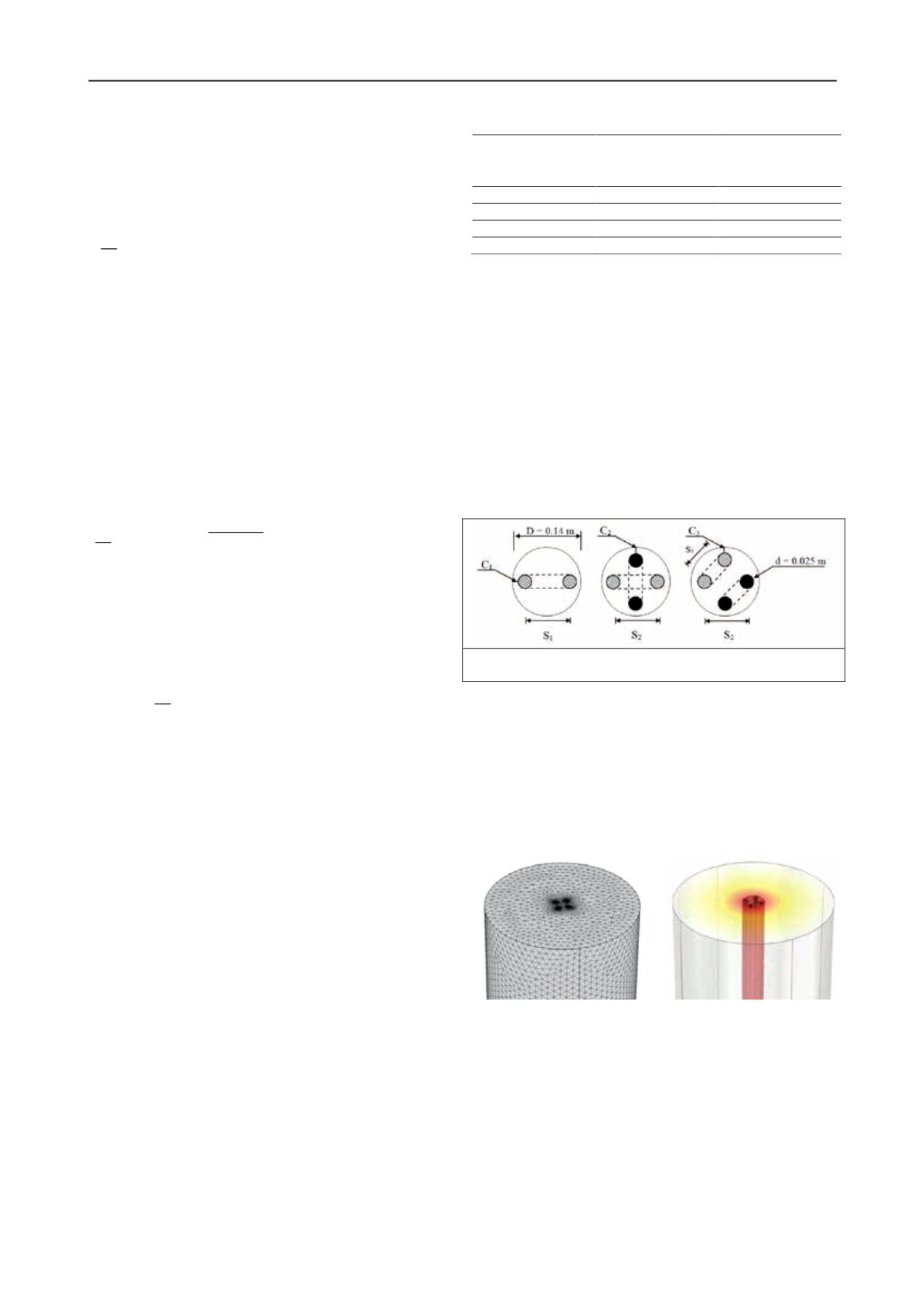
A single, double or double cross HDPE U-pipe GHE with a
pipe diameter of 0.025 m and wall thickness of 0.003 m is
sequentially modelled to assess the thermal response of these
different pipe configurations. The pipe separation (i.e., distance
between inlet and outlet pipes) is set at its maximum value; in
the other words, pipes are placed as close as possible to the
borehole wall. This is known to render higher thermal efficiency
than more closely spaced pipe placements and is common
installation practice. The pipe cover, C, is kept equal in all cases
modelled here (i.e., C
1
= C
2
= C
3
). Therefore, the GHEs
embedding single and double cross U-pipes have the same pipe
separation S
1
= S
2
= 0.11 m, but due to geometry limitations, the
pipe separation reduces to S
3
= 0.07 m in double U-pipe settings
(see Figure 1). A soil cylinder with a diameter of 7 m
surrounding the GHE completes the FEM model.
(a) (b) (c)
Figure 1. GHE pipe configurations: (a) single U-pipe, (b) double cross
U-pipe, (c) double U-pipe.
A 5-day transient study with prescribed fluid flow rates
varying from laminar to turbulent regime is conducted on these
different GHE configurations. The recommended FEM mesh
pattern consists of elements with higher mesh density near and
in the pipes, becoming coarser in the radial direction, away from
the center of the GHE and towards the ground. Figure 2 shows
an example of a 3D model configuration and FEM mesh pattern
for a GHE with two U-pipes.
(a)
(b)
Figure 2. Example of a 3D FEM model section: (a) FEM mesh of a
GHE with two U-pipes; (b) detail of temperature distribution.
2.1.2
Numerical modelling of large diameter GHEs with
spiral pipes and multiple U-pipes
The numerical models consist of 30 m long cylindrical vertical
GHEs, 0.46 m in diameter, comprising spiral and straight HDPE
pipes embedded in grout. The GHE is surrounded by a soil
cylinder of 7 m diameter.
A larger borehole diameter will be typically (but not always)
required when HDPE pipes are used in a spiral configuration
due to the stiffness of the pipe. GHEs with spiral pipes and with
single, double or triple U-pipes are modelled for comparision.


