3346
Proceedings of the 18
th
International Conference on Soil Mechanics and Geotechnical Engineering, Paris 2013
to implement as with U-pipes due to HDPE pipe stiffness, and
(ii) they have nearly the same thermal performance. In these
large diameter GHEs, a relatively minor change in heat
extraction rate is suggested by the numerical results when the
total the flow rate through the GHE is increased. The rightmost
column in Table 3 summarises the numerical results of doubling
and tripling the flow rates in GHE with double U-pipes and
triple U-pipes respectively (the same fluid flow rate is applied to
each U-loop of the GHEs).
Figure 5. Heat extraction rate and outlet temperature in a spiral GHE
with different axial pitches.
Table 3. Comparison of spiral and U-pipes GHE thermal performance
for varying pipe lengths.
Geometry
Axial
Pitch
[m]
Pipe
length
[m]
Flow rate
of 14.5 l/min in
each GHE
Flow rate of
14.5 l/min in
each U-pipe
Heat extraction
rate [W/m]
Heat extraction
rate [W/m]
Spiral 1
0.2
180
48.63
48.63
Triple U
-
180
49.71
51.15
Spiral 2
0.3
120
45.35
45.35
Double U
-
120
44.07
45.10
Spiral 3
1
60
37.13
37.13
Single U-pipe
-
60
32.53
32.53
The previous observations will not vary significantly if
different pipe separations in the U-pipes are used. To investigate
the effects of pipe separation on GHEs thermal performance,
single, double and triple U-pipes with different inlet-outlet pipe
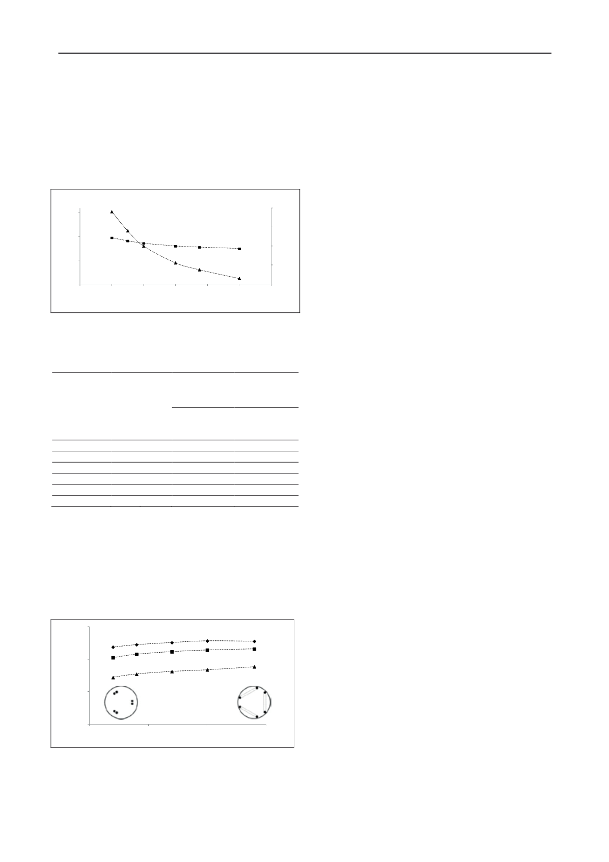
separations were simulated. Figure 6 shows variations of pipe
separation for multiple U-pipe GHEs and how this affects the
heat extraction rate. Pipe separation variations between S
S
=
0.04 m and S
L
= 0.28 m for the 0.46 m diameter GHE result in
heat extraction rate increasing about 7% to 23%.
Figure 6. Effect of pipe separation on heat extraction rate for GHEs with
single, double and triple u-pipes.
It is worth mentioning that pipe separation has a stronger
influence on GHEs with single U-pipe than that of a triple U-
pipe, the reason being that in multiple U-pipes, increasing the
separation reduces the thermal interference between inlet and
outlet pipe of one U-pipe but at the same time increases mutual
interference between different U-pipes inside the GHE.
4 CONCLUSIONS
The outcomes of the multiple simulations performed in this
work show that GHE configuration may affect system
efficiency. Based on numerical results in a large diameter
borehole and for a given borehole length, it seems that as long
as the same pipe length is embedded inside the borehole,
thermal performance of the system is not significantly related to
pipe geometry placement, at least for the spiral and multiple U-
pipes analysed here. However, comparison of small diameter
GHEs with double and double cross U-pipe shows between 8%
to 23% better performance of the former one. Nevertheless, the
addition of a second U-pipe to both small and large diameter
GHEs achieves significant (40-90%) additional thermal
performance and could lead to important cost savings when
compared with single pipe systems due to reduced drilling
costs.
Heat extraction rates tend to increase rapidly as the Reynolds
number increases in the laminar regime; however, the rate of
increase reduces with Reynolds numbers once the flow becomes
turbulent. This indicates that when considering the size of the
fluid circulating pump and its operational cost, highly turbulent
fluid flow will not necessarily result in a more efficient system
overall. Regardless of number of U-pipes inside the GHE, larger
pipe separation improves the system efficiency. However, as the
number of U-pipes in the GHE increases, this effect becomes
less pronounced due to thermal interference occurring between
different U-pipes.
5 ACKNOWLEDGEMENTS
This work is partially supported by funding of $1.6 M from
the Victorian Government’s Energy Technology Innovation
Strategy (ETIS) Pilot Demonstration Program (SEPD) and The
University of Melbourne’s Research Collaboration Grant.
6 REFERENCES
Banks, D. 2008. An introduction to thermogeology: ground source
heating and cooling, Wiley-Blackwell.
Bernier, M.A. 2001. Ground-coupled heat pump system simulation.
ASHRAE Transactions
107, 605-616.
Deerman, J. 1990. Simulation of vertical U-tube ground-coupled heat
pump systems using the cylindrical heat source solution.
ASHRAE
Transaction: Research
3472, 287-295.
Gao, J., X. Zhang, J. Liu, K.S. Li and J. Yang 2008. Thermal
performance and ground temperature of vertical pile-foundation
heat exchangers: A case study.
Applied Thermal Engineering
28(17), 2295-2304.
Hamada, Y., H. Saitoh, M. Nakamura, H. Kubota and K. Ochifuji 2007.
Field performance of an energy pile system for space heating.
Energy and Buildings
39(5), 517-524.
Jun, L., Z. Xu, G. Jun and Y. Jie 2009. Evaluation of heat exchange rate
of GHE in geothermal heat pump systems.
Renewable Energy
34(12), 2898-2904.
Lamarche, L. and B. Beauchamp 2007. A new contribution to the finite
line-source model for geothermal boreholes.
Energy and Buildings
39(2), 188-198.
Marcotte, D. and P. Pasquier 2008. Fast fluid and ground temperature
computation for geothermal ground-loop heat exchanger systems.
Geothermics
37(6), 651-665.
Miyara, A., K. Tsubaki, S. Inoue and K. Yoshida 2011. Experimental
study of several types of ground heat exchanger using a steel pile
foundation.
Renewable Energy
36(2), 764-771.
6.1
6.2
6.3
6.4
6.5
0
25
50
75
0
0.2
0.4
0.6
0.8
1
1.2
T
out
[
°
C]
Heat extraction rate [W/m]
Axial pitch [m]
0
20
40
60
0.00
0.10
0.20
0.30
Heat extraction rate [W/m]
Pipe separation [m]
HER
T
out
Single
Double
Triple
S
S
S
L


