2718
Proceedings of the 18
th
International Conference on Soil Mechanics and Geotechnical Engineering, Paris 2013
5
LOAD TESTS OF INDIVIDUAL PILES.
In order to verify the design assumptions as well as to meet
general recommendations regarding pile foundations, the
bearing capacity of piles was investigated by static load tests.
Due to importance of the construction as well as from the
design assumptions, the load tests program was extended (after
the agreement of the designer and investor). In order to examine
the effectiveness of the pile base improvement by injection as
well to control its quality, one of piles designated for testing
was installed without the injection. Additionally, in three of the
test piles, extensometer measuring system to control the
distribution of force along the pile was installed. The goal of
these measurements was to investigate the distribution of load
transmitted by the pile shaft and base. It is also useful to assess
the force generated at the pile base due to injection.
Additionally, extensometer measurements were planned for the
case of unfavorable bearing capacity test results. The
measurement results would be useful for the analysis of the
reasons of too low bearing capacity (shaft of pile or its base).
The extensometers were installed at seven levels distributed
along the pile length.
0
5
10
15
20
25
30
35
0
2000
4000
6000
8000
10000
12000
Q [kN]
s [mm]
Piles No62, 71, 74
(with base injection)
Pile No 99
(without base injection)
Figure 7:
Pile load test results
Pile load tests were carried out according to the standard
procedure i.e. to the maximum force
Q
max
= 11000 kN with
intermediate unloading at the force
Q
1
=
Q
r
= 7400 kN. The
results of load tests confirmed the need of extended measuring
program. The gained information proved the safety of the
current and future foundation work. The important observation
was proper work of the piles with injection and their advantage
over the pile without base improvement. It is well visible in
Fig. 7 where respective load-settlement curves are shown. The
results of extensometric measurements in the form of
distribution of force along the piles are shown in Fig. 8. They
allowed for the examination of the work of the piles in the
existing soil conditions. The essential portion of force was
transmitted by the pile shaft what corresponded to the assumed
concept of piles in the raft foundation system.
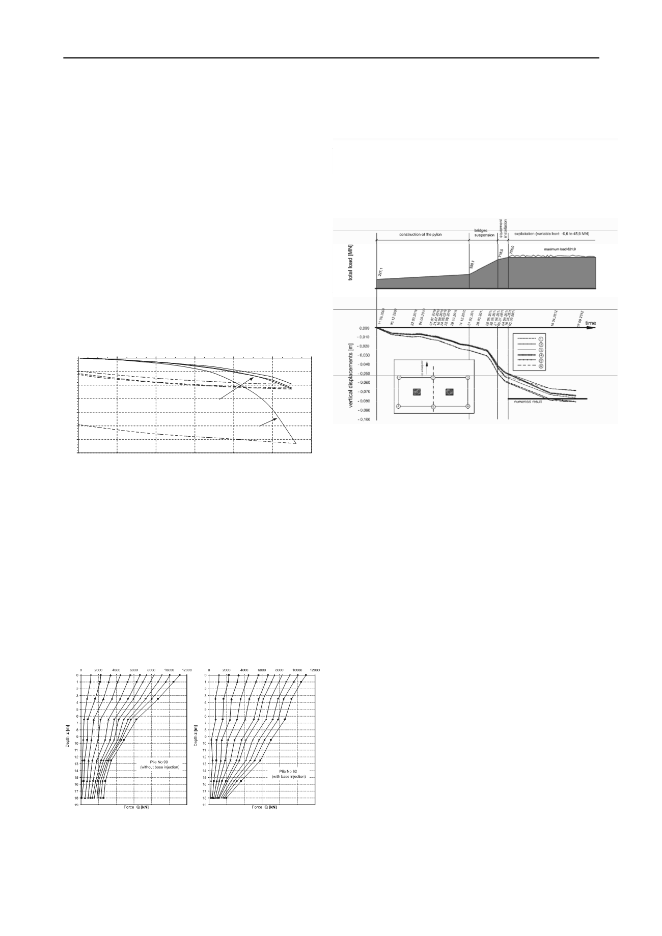
Figure 8:
Distribution of forces along the pile form the
extensometric measurements.
6
FIELD MEASUREMENTS
After piling and pylon slab construction, six benchmarks
were placed on the slab surface in characteristic points (see
figure X). Since 11.09.2009 till now the vertical displacements
of foundation are geodetically monitored. After every stage of
bridge loading vertical displacement were measured. Currently
bridge is fully loaded, and settlements are in a stabilisation
phase. Good agreement between measured displacements and
numerical analysis results is observed (see Fig. 9).
Figure 9:
Settlements of foundation slab measured in 6 points in
different phases of pylon loading.
7
SUMMARY
In the paper analysis of the raft foundation supporting the
pylon of cable-stayed bridge in Rędzin being the part of
Wrocław motorway A8 ring is briefly presented. Important
decision related to the selection of the pile length was their
shortening due to occurrence of confined aquifers which would
cause the liquefaction of soils under the pile bases during
installation. The decision could be undertaken after
comprehensive numerical analyses as well as additional, non-
standard investigations of soil parameters. Load tests with the
measurement of the distribution of force along the piles with
extensometers were very useful, allowing the control of design
assumptions. The field measurements and their agreement with
numerical analyses results are the best proof that assumptions
made in the design process were correct.
8
REFERENCES
Atkinson, J.H.
Non-linear Soil Stiffness in Routine Design
, 40
th
Rankin
Lecture, “Geotechnique”, 2000, vol. 50 No. 5, 487-508.
Geological report (1), A-8 Motorway, AOW, GeoTech Ltd. Rzeszów
2006, (in Polish).
Kosecki M.:
Static of piling structures
, PZTB Szczecin branch, 2006,
(in Polish).
Elaboration the way of foundation of the P14 support of cable-stayed
bridge pylon in the motorway ring (A8) over the Odra river in
Wrocław
, Geosyntex Ltd., Gdynia 2008, (in Polish).
Santos, J.A, Correia A.G.:
Reference Threshold Shear Strain of Soils, Its
Application to obtain a Unique Strain-Dependent Shear Modulus
Curve for soil.
Proc. The 15
th
Int. Conf. On Soil Mech and Geot.
Eng., Instanbul, 2000, vol. 1, 267-270.
Geological report (2) on the geotechnical and laboratory investigations
under the pylon and permanent supports for construction of cable-
stayed bridge over the Odra River in Wroclaw, Geoteko - Design
and Geotechnical Consulting Ltd., Warszawa, 2008, (in Polish).
5
LOAD TESTS OF INDIVIDUAL PILES.
In order to verify the design assumptions as well as to meet
general recommendations regarding pile foundations, the
bearing capacity of piles was investigated by static load tests.
Due to importance of the construction as well as from the
design assumptions, the load tests program was extended (after
the agreement of the designer and investor). In order to examine
the effectiveness of the pile base improvement by injection as
well to control its quality, one of piles designated for testing
was installed without the injection. Additionally, in three of the
test piles, extensometer measuring system to control the
distribution of force along the pile was installed. The goal of
these measurements was to investigate the distribution of load
transmitted by the pile shaft and base. It is also useful to assess
the force generated at the pile base due to injection.
Additionally, extensometer measurements were planned for the
case of unfavorable bearing capacity test results. The
measurement results would be useful for the analysis of the
reasons of too low bearing capacity (shaft of pile or its base).
The extensometers were installed at seven levels distributed
along the pile length.
0
5
10
15
20
25
30
35
0
2000
4000
6000
8000
10000
12000
Q [kN]
s [mm]
Piles No62, 71, 74
(with base injection)
Pile No 99
(without base injection)
Figure 7:
Pile load test results
Pile load tests were carried out according to the standard
procedure i.e. to the maximum force
Q
max
= 11000 kN with
intermediate unloading at the force
Q
1
=
Q
r
= 7400 kN. he
results of load tests confirmed the need of extended measuring
program. The gained information proved the safety of the
current and future foundation work. The important observation
was proper work of the piles with injection and their advantage
over the pile without base improvement. It is well visible in
Fig. 7 where respective load-settlement curves are shown. The
results of extensometric measurements in the form of
distribution of force along the piles are shown in Fig. 8. They
allowed for the examination of the work of the piles in the
existing soil conditions. The essential portion of force was
transmitted by the pile shaft what corresponded to the assumed
concept of piles in the raft foundation system.
Figure 8:
Distribution of forces along the pile form the
extensometric measurements.
6
FIELD MEASUREMENTS
After piling and pylon slab construction, six benchmarks
were placed on the slab surface in characteristic points (see
figure X). Since 11.09.2009 till now the vertical displacements
of foundation are geodetically monitored. After every stage of
bridge loading vertical displacement were measured. Currently
bridge is fully loaded, and settlements are in a stabilisation
phase. Good agreement between measured displacements and
numerical analysis results is observed (see Fig. 9).
Figure 9:
Settlements of foundation slab measured in 6 points in
different phases of pylon loading.
7
SUMMARY
In the paper analysis of the raft foundation supporting the
pylon of cable-stayed bridge in Rędzin being the part of
Wrocław motorway A8 ring is briefly presented. Important
decision related to the selection of the pile length was their
shortening due to occurrence of confined aquifers which would
cause the liquefaction of soils under the pile bases during
installation. The decision could be undertaken after
comprehensive numerical analyses as well as additional, non-
standard investigations of soil parameters. Load tests with the
measurement of the distribution of force along the piles with
extensometers were very useful, allowing the control of design
assumptions. The field measurements and their agreement with
numerical analyses results are the best proof that assumptions
made in the design process were correct.
8
REFERENCES
Atkinson, J.H.
Non-linear Soil Stiffness in Routin Design
, 40
th
Rank
Lecture, “ technique”, 2000, vol. 50 No. 5, 487-508.
Geological report (1), A-8 Motorway, AOW, GeoTech Ltd. Rze zów
2006, (in Polish).
Kosecki M.:
Stat c of piling structures
, PZTB Szczecin branch, 2006,
(i Poli h).
Elab ration the way f foundation of the P14 support of cable-stayed
bridge pylon i the motorway ring (A8) over the Odra river in
Wrocław
, G osyntex Ltd., Gdynia 2008, (in Polish).
Santos, J.A, Corre a A.G.:
Reference Threshold Shear Strain f Soils, Its
Application to obtain a Unique Strain-Dependent Shear Modulus
Curve for soil.
Proc. The 15
th
Int. Conf. On Soil Mech and Geot.
Eng., Instanbul, 2000, vol. 1, 267-270.
Geological report (2) on the geotechnical and laboratory investigations
under the pylon and permanent supports for construction of cable-
stayed bridge over the Odra River in Wroclaw, Geoteko - Design
distribution of force along the pile was installed. The goal of
these measurements was to investigate the distribution of load
transmitted by the pile shaft and base. It is also useful to assess
the force generated at the pile base due to injection.
Additionally, extensometer measurements were planned for the
case of unfavorable bearing capacity test results. The
measurement results would be useful for the analysis of the
reasons of too low bearing capacity (shaft of pile or its base).
The extensometers were installed at seven levels distributed
along the pile length.
0
5
10
15
20
25
30
35
0
2000
4000
6000
8000
10000
12000
Q [kN]
s [mm]
Piles No62, 71, 74
(with base injection)
Pile No 99
(without base injection)
Figure 7:
Pile load test results
Pile load tests were carried ut accordin to the standard
procedure i.e. to the maximum force
Q
max
= 11000 kN with
intermediate unloading at th for e
Q
1
=
Q
r
= 7400 kN.
re ults of load tests confirmed the need f exten ed measuring
program. Th gained i f rmation proved the safety of the
current a futur foundation work. Th important ob e vation
was prop r work of the piles with injection and their advantage
over the pile without base improve ent. It is well visible in
Fig. 7 where respective load-settlement curves are shown.
results of extensometric m asurements in the form of
distribution f f rce along the piles are shown in Fig. 8. Th y
allowed for the examination of the work of th piles in the
existing soil conditions. The essential portion of force was
transmitted by the pile shaft what corresponded to the assumed
concept of piles in the raft foundation system.
Figure 8:
Distribution of forces along the pile form the
extensometric measurem nts.
figure X). Since 11.09.2009 till now the vertical displacements
of foundation are geodetically monitored. After every stage of
bridge loading vertical displacement were measured. Currently
bridge is fully loaded, and settlements are in a stabilisation
phase. Good agreement between meas red displacements and
numeric l analysis results i observed (see Fig. 9).
Figure 9:
Settlements of foundation slab measured in 6 points in
different phases of pylon loading.
7
SUMMARY
In the paper analysis of the raft foundation supporting the
pylon of cable-stayed bridge in Rędzin being the part of
Wrocław motorway A8 ring is briefly presented. Important
decision related to the selection of the pile length was their
shortening due to occurrence of confined aquifers which would
cause the liquefaction of soils under the pile bases during
installation. The decision c uld be undertaken after
comprehensive numerical nalyses as well as additional, non-
standard investiga ons of soil paramet s. Load t sts with he
measurement of the istribution of force along the pile with
extensometers w re very useful, allowing the control of design
assumptions. The fi ld measurements and their agreement with
numerical analyses results are the best proof that assumptions
mad in the design process were correct.
8
REFERENCES
Atkinson, J.H.
Non-linear Soil Stiffness in Routine Design
, 40
th
Rankin
Lecture, “Geotechnique”, 2000, vol. 50 No. 5, 487-508.
Geological report (1), A-8 Motorway, AOW, GeoTech Ltd. Rzeszów
2006, (in Polish).
Kosecki M.:
Static of piling structures
, PZTB Szczecin branch, 2006,
(in Polish).
Elaboration the way of foundation of the P14 support of cable-stayed
bridge pylon in the motorway ring (A8) over the Odra river in
Wrocław
, Geosyntex Ltd., Gdynia 2008, (in Polish).
Santos, J.A, Correia A.G.:
Reference Threshold Shear St ain of Soils, Its
Application to obtain U ique Str in-Dependent Shear Modulus
Curve for soil.
Proc. The 15
th
Int. Conf. On Soil Mech and Geot.
Eng., Instanbul, 2000, vol. 1, 267-270.
Geological report (2) on the geotechnical and laboratory investigations
under the pylon and permanent supports for construction of cable-
stayed bridge over the Odra River in Wroclaw, Geoteko - Design
nd Geotechnical Consulting Ltd., Warszawa, 2008, (in Polish).


